 |
Motor de Búsqueda de Datasheet de Componentes Electrónicos |
|
|
Motor de Búsqueda de Datasheet de Componentes Electrónicos |
|
The question interval is too short.
Please try again in a few seconds.

Hello, Please ask a question about AP3418 Datasheet
# Example questions:
➢ What is the operating temperature range for the ap3418 in the sot25 package?
➢ What packing options are available for the ap3418, and what does the 'g1' suffix in the part number indicate?
➢ In the 'enable turn on' and 'enable turn off' performance characteristics, what parameters are being measured on the vertical (y) axis with a 5v/div scale?
| Part No. | AP3418 |
| Manufacturer | DIODES |
| Size | 522 Kbytes |
| Pages | 11 pages |
| Description | HIGH EFFICIENCY SYNCHRONOUS DC-DC BUCK CONVERTER |






1. General Information and Features (Pages 1-2 - Not Visible in Image)
️· Likely includes a brief description of the AP3418: its purpose (power conversion), target applications (not shown, but probably portable devices, battery-powered systems), and key features.
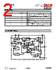
2. Typical Applications and Block Diagram (Pages 3-4 - Not Visible in Image)
️· Illustrations of the AP3418 in typical circuit designs, showing how it's connected and used.
️· A block diagram outlining the IC's internal architecture - key components and their relationships.
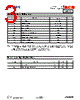
3. Absolute Maximum Ratings (Page 1)
️· Lists the maximum ratings for various electrical parameters (voltage, current, power) that the IC can safely handle. Exceeding these ratings can damage the device.
4. Electrical Characteristics (Pages 1-4)
️· A *lot* of data on the IC's behavior under different conditions (voltage, temperature, load). Key values include:
- Input Voltage Range
- Output Voltage
- Efficiency
- Quiescent Current (current drawn when not actively switching)
- Switching Frequency
- Voltage Ripple
️· This is critical for engineers to verify the AP3418's suitability for a specific application.
5. Typical Performance Curves (Pages 2-6)
️· Graphs: These show how the electrical characteristics (e.g., efficiency, output voltage, quiescent current) change with parameters like input voltage, output current, and temperature. They are visually represent performance.
6. Timing Diagrams (Pages 4-7)
️· Illustrations showing how the AP3418 responds to signals over time.
- Enable Turn-on/Off Timing: Shows how long it takes for the IC to start and stop regulating the output voltage.
- Short-Circuit Protection: Demonstrates the IC's behavior during a short-circuit condition (how it protects itself).
- Recovery Time: Shows how long it takes for the IC to recover from a short circuit.
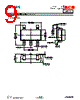
7. Package Information (Pages 7-9)
️· Package Outline Dimensions: Detailed drawings of the SOT-25 package (the IC's physical housing). This is essential for PCB layout and manufacturing.
️· Suggested Pad Layout: Guidelines for the size and placement of the soldering pads on the printed circuit board (PCB) to ensure proper electrical connections and thermal dissipation.
8. Ordering Information (Page 10)
️· Lists the available part numbers for the AP3418, including packaging options (Tape & Reel) and temperature range.
️· Marking Information: Indicates the code printed on the IC itself for identification.
9. Revision History (Not Visible)
️· Details any changes made to the datasheet over time.
Key Takeaways & What to Look For If You're an Engineer:
️· Efficiency: How much power is delivered to the output vs. drawn from the input. Higher is better.
️· Quiescent Current (Iq): The current the IC consumes when it's not switching. Lower is better for battery life.
️· Voltage Range: The range of input voltages the IC can handle.
️· Thermal Considerations: The datasheet provides information to guide thermal management.
1. General Information and Features (Pages 1-2 - Not Visible in Image)
️· Likely includes a brief description of the AP3418: its purpose (power conversion), target applications (not shown, but probably portable devices, battery-powered systems), and key features.
2. Typical Applications and Block Diagram (Pages 3-4 - Not Visible in Image)
️· Illustrations of the AP3418 in typical circuit designs, showing how it's connected and used.
️· A block diagram outlining the IC's internal architecture - key components and their relationships.
3. Absolute Maximum Ratings (Page 1)
️· Lists the maximum ratings for various electrical parameters (voltage, current, power) that the IC can safely handle. Exceeding these ratings can damage the device.
4. Electrical Characteristics (Pages 1-4)
️· A *lot* of data on the IC's behavior under different conditions (voltage, temperature, load). Key values include:
- Input Voltage Range
- Output Voltage
- Efficiency
- Quiescent Current (current drawn when not actively switching)
- Switching Frequency
- Voltage Ripple
️· This is critical for engineers to verify the AP3418's suitability for a specific application.
5. Typical Performance Curves (Pages 2-6)
️· Graphs: These show how the electrical characteristics (e.g., efficiency, output voltage, quiescent current) change with parameters like input voltage, output current, and temperature. They are visually represent performance.
6. Timing Diagrams (Pages 4-7)
️· Illustrations showing how the AP3418 responds to signals over time.
- Enable Turn-on/Off Timing: Shows how long it takes for the IC to start and stop regulating the output voltage.
- Short-Circuit Protection: Demonstrates the IC's behavior during a short-circuit condition (how it protects itself).
- Recovery Time: Shows how long it takes for the IC to recover from a short circuit.
7. Package Information (Pages 7-9)
️· Package Outline Dimensions: Detailed drawings of the SOT-25 package (the IC's physical housing). This is essential for PCB layout and manufacturing.
️· Suggested Pad Layout: Guidelines for the size and placement of the soldering pads on the printed circuit board (PCB) to ensure proper electrical connections and thermal dissipation.
8. Ordering Information (Page 10)
️· Lists the available part numbers for the AP3418, including packaging options (Tape & Reel) and temperature range.
️· Marking Information: Indicates the code printed on the IC itself for identification.
9. Revision History (Not Visible)
️· Details any changes made to the datasheet over time.
Key Takeaways & What to Look For If You're an Engineer:
️· Efficiency: How much power is delivered to the output vs. drawn from the input. Higher is better.
️· Quiescent Current (Iq): The current the IC consumes when it's not switching. Lower is better for battery life.
️· Voltage Range: The range of input voltages the IC can handle.
️· Thermal Considerations: The datasheet provides information to guide thermal management.
| Part No. | AP3418 |
| Manufacturer | DIODES |
| Size | 522 Kbytes |
| Pages | 11 pages |
| Description | HIGH EFFICIENCY SYNCHRONOUS DC-DC BUCK CONVERTER |
| ¿ALLDATASHEET es útil para Ud.? [ DONATE ] |
Todo acerca de Alldatasheet | Publicidad | Contáctenos | Política de Privacidad | Enlace a la hoja de datos | Intercambio de Enlaces | Lista de Fabricantes All Rights Reserved©Alldatasheet.com |
| Russian : Alldatasheetru.com | Korean : Alldatasheet.co.kr | Spanish : Alldatasheet.es | French : Alldatasheet.fr | Italian : Alldatasheetit.com Portuguese : Alldatasheetpt.com | Polish : Alldatasheet.pl | Vietnamese : Alldatasheet.vn Indian : Alldatasheet.in | Mexican : Alldatasheet.com.mx | British : Alldatasheet.co.uk | New Zealand : Alldatasheet.co.nz |
|
Family Site : ic2ic.com |
icmetro.com |
 Mexican ▼
  English
 Chinese
 German
 Japanese
 Russian
 Korean
 Spanish
 French
 Italian
 Portuguese
 Polish
 Vietnamese
 Indian
 British
 New Zealand