 |
Motor de Búsqueda de Datasheet de Componentes Electrónicos |
|
|
Motor de Búsqueda de Datasheet de Componentes Electrónicos |
|
The question interval is too short.
Please try again in a few seconds.

Hello, Please ask a question about MAS6179A1 Datasheet
# Example questions:
➢ What is the purpose of connecting the nc (not connected) pins to vss, and why is pin 6 specifically mentioned in the documentation?
➢ Describe the fast startup feature of the mas6179, including the conditions required for it to operate correctly.
➢ What is the function of the aon pin, and what happens when it is set to vss versus vdd?
| Part No. | MAS6179A1 |
| Manufacturer | MAS |
| Size | 130 Kbytes |
| Pages | 10 pages |
| Description | AM Receiver IC |





1. Overview:
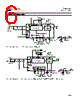
️· Chip Type: Tri-Band AM Receiver IC (Integrated Circuit) with a differential input. Designed for receiving long-wave (LW), medium-wave (MW), and short-wave (SW) AM radio signals.
️· Key Features:
- Differential input for improved noise rejection.
- Quartz filter outputs for selectable crystal filters.
- Automatic Gain Control (AGC) for optimized reception.
- Power-down mode for low power consumption.
- Fast start-up.
- Selectable capacitor option.
2. Functional Description:
️· Reception: The chip converts radio waves into a voltage signal, with an important role for the ferrite antenna.
️· AGC: The AGC circuit automatically adjusts the amplification level to compensate for signal strength variations.
️· Power Management:
- Power-Down Mode: Controlled by the PDN1 and PDN2 inputs. Both high (VDD) turns the receiver OFF.
- Fast Startup: Automatic when transitioning from power-down to active, requiring the VDD to be high. Takes around 1-2 seconds to startup.
3. Pinout and Functions:
️· Power:
- VDD: Positive power supply.
- VSS: Ground.
️· Outputs:
- QO1, QO2, QO3: Quartz filter outputs for selectable crystal filters.
- OUT: Receiver output (current source/sink). Pulled to VSS in power down mode.
️· Inputs:
- QI: Quartz filter input. Must be connected to VSS.
- AGC: AGC capacitor.
- PDN1, PDN2: Power down/frequency selection inputs.
- DEC: Demodulator capacitor.
- AON: AGC On/Hold control. Internal pull-up; VSS = AGC Off (Hold), VDD = AGC On.
- RFI2, RFIP, RFIM: Receiver inputs (differential).
️· Other:
- NC: Not Connected – Should be connected to VSS to minimize noise.
4. Key Control Signals & Features:
️· PDN1/PDN2: These control the power-down state. To turn on the receiver, at least one of these needs to be low.
️· AON: Controls the AGC circuit – Hold or Release.
️· AGC Circuit: Automatic gain control. AON controls the release and hold states.
️· Fast Startup: Activated upon transitioning from power-down to active.
5. Antenna:
️· Importance: A crucial element for performance.
️· Characteristics: Recommended impedance at resonance is around 150 kΩ. Quality factor (Q) should be approximately 100.
6. Ordering Information:
️· MAS6179A1TC00: CC = 0.75 pF capacitor option.
️· MAS6179A2TC00: CC = 1.3 pF capacitor option.
Important Notes & Cautions:
️· NC Pins: Connect NC pins to VSS to reduce noise.
️· QI Pin: Must be connected to VSS.
️· Startup Conditions: Ensure VDD is high before powering on after power-down.
️· AON Control: Use the AON pin to hold and release the AGC circuit, especially during periods of disturbance (e.g., stepper motor operation).
️· Antenna: Proper antenna selection and impedance matching are critical for optimal performance.
1. Overview:
️· Chip Type: Tri-Band AM Receiver IC (Integrated Circuit) with a differential input. Designed for receiving long-wave (LW), medium-wave (MW), and short-wave (SW) AM radio signals.
️· Key Features:
- Differential input for improved noise rejection.
- Quartz filter outputs for selectable crystal filters.
- Automatic Gain Control (AGC) for optimized reception.
- Power-down mode for low power consumption.
- Fast start-up.
- Selectable capacitor option.
2. Functional Description:
️· Reception: The chip converts radio waves into a voltage signal, with an important role for the ferrite antenna.
️· AGC: The AGC circuit automatically adjusts the amplification level to compensate for signal strength variations.
️· Power Management:
- Power-Down Mode: Controlled by the PDN1 and PDN2 inputs. Both high (VDD) turns the receiver OFF.
- Fast Startup: Automatic when transitioning from power-down to active, requiring the VDD to be high. Takes around 1-2 seconds to startup.
3. Pinout and Functions:
️· Power:
- VDD: Positive power supply.
- VSS: Ground.
️· Outputs:
- QO1, QO2, QO3: Quartz filter outputs for selectable crystal filters.
- OUT: Receiver output (current source/sink). Pulled to VSS in power down mode.
️· Inputs:
- QI: Quartz filter input. Must be connected to VSS.
- AGC: AGC capacitor.
- PDN1, PDN2: Power down/frequency selection inputs.
- DEC: Demodulator capacitor.
- AON: AGC On/Hold control. Internal pull-up; VSS = AGC Off (Hold), VDD = AGC On.
- RFI2, RFIP, RFIM: Receiver inputs (differential).
️· Other:
- NC: Not Connected – Should be connected to VSS to minimize noise.
4. Key Control Signals & Features:
️· PDN1/PDN2: These control the power-down state. To turn on the receiver, at least one of these needs to be low.
️· AON: Controls the AGC circuit – Hold or Release.
️· AGC Circuit: Automatic gain control. AON controls the release and hold states.
️· Fast Startup: Activated upon transitioning from power-down to active.
5. Antenna:
️· Importance: A crucial element for performance.
️· Characteristics: Recommended impedance at resonance is around 150 kΩ. Quality factor (Q) should be approximately 100.
6. Ordering Information:
️· MAS6179A1TC00: CC = 0.75 pF capacitor option.
️· MAS6179A2TC00: CC = 1.3 pF capacitor option.
Important Notes & Cautions:
️· NC Pins: Connect NC pins to VSS to reduce noise.
️· QI Pin: Must be connected to VSS.
️· Startup Conditions: Ensure VDD is high before powering on after power-down.
️· AON Control: Use the AON pin to hold and release the AGC circuit, especially during periods of disturbance (e.g., stepper motor operation).
️· Antenna: Proper antenna selection and impedance matching are critical for optimal performance.
| Part No. | MAS6179A1 |
| Manufacturer | MAS |
| Size | 130 Kbytes |
| Pages | 10 pages |
| Description | AM Receiver IC |
| ¿ALLDATASHEET es útil para Ud.? [ DONATE ] |
Todo acerca de Alldatasheet | Publicidad | Contáctenos | Política de Privacidad | Enlace a la hoja de datos | Intercambio de Enlaces | Lista de Fabricantes All Rights Reserved©Alldatasheet.com |
| Russian : Alldatasheetru.com | Korean : Alldatasheet.co.kr | Spanish : Alldatasheet.es | French : Alldatasheet.fr | Italian : Alldatasheetit.com Portuguese : Alldatasheetpt.com | Polish : Alldatasheet.pl | Vietnamese : Alldatasheet.vn Indian : Alldatasheet.in | Mexican : Alldatasheet.com.mx | British : Alldatasheet.co.uk | New Zealand : Alldatasheet.co.nz |
|
Family Site : ic2ic.com |
icmetro.com |
 Mexican ▼
  English
 Chinese
 German
 Japanese
 Russian
 Korean
 Spanish
 French
 Italian
 Portuguese
 Polish
 Vietnamese
 Indian
 British
 New Zealand