 |
Motor de Búsqueda de Datasheet de Componentes Electrónicos |
|
|
Motor de Búsqueda de Datasheet de Componentes Electrónicos |
|
The question interval is too short.
Please try again in a few seconds.

Hello, Please ask a question about AD7839 Datasheet
# Example questions:
➢ How are the eight dacs selected for data loading, and what address line combination corresponds to selecting dac g?
➢ What is the function of the _clr_ pin in the ad7839, and what happens to the dac outputs when this pin is activated?
➢ What causes dc crosstalk in the ad7839, and how can it be minimized?
| Part No. | AD7839 |
| Manufacturer | AD |
| Size | 153 Kbytes |
| Pages | 12 pages |
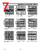
| Description | Octal 13-Bit, Parallel Input, Voltage-Output DAC |




1. Overview
️· The AD7839 is an 8-channel, 13-bit voltage-mode Digital-to-Analog Converter (DAC).
️· It allows for independent control of each DAC channel.
️· It's designed for applications needing multiple, precisely controlled analog outputs.
2. Features
️· 8 Independent Channels: Each channel is fully controllable.
️· 13-Bit Resolution: Provides a wide dynamic range and precision.
️· Straight Binary Coding: Simple and predictable output relationship.
️· Voltage-Mode Architecture: Efficient and accurate analog output generation.
️· Addressable Channels: A0, A1, and A2 inputs select which channel receives data.
️· Asynchronous Clear (CLR): All outputs are forced to the DUTGND voltage level.
️· Level-Triggered Inputs: CS (Chip Select) and WR (Write) are level-triggered.
️· Flexible Loading: Data is loaded in straight parallel 13-bit words.
3. Terminology (Key Definitions)
️· Relative Accuracy (Endpoint Linearity): Deviation from a straight-line transfer function.
️· Differential Nonlinearity (DNL): Difference between actual output changes vs. ideal 1 LSB changes. A specified DNL ensures monotonicity (outputs increase with increasing digital input).
️· DC Crosstalk: Small variations in one channel's output due to changes in another. (Primarily due to shared power supply.)
️· Output Voltage Settling Time: How long it takes for the output to reach a specific level after a digital input change.
️· Digital-to-Analog Glitch Impulse: Unwanted "noise" during conversion (measured in nV-secs).
️· Channel-to-Channel Isolation: How well one channel's output is isolated from another.
️· DAC-to-DAC Crosstalk: Glitch impulse appearing at the output of one converter due to changes in another.
️· Digital Feedthrough: Noise on the outputs due to high-frequency logic activity.
️· Full-Scale Error: Error when all bits are set to '1'.
️· Zero-Scale Error: Error when all bits are set to '0'.
️· Gain Error: Difference between Full-Scale and Zero-Scale Error.
4. Operation
️· Addressing Channels: The A0, A1, and A2 inputs determine which DAC channel's input register receives data.
- Table I clearly defines the channel selection based on address line logic.
️· Writing Data:
- Data is loaded in 13-bit parallel words.
- The CS (Chip Select) must be low, and a low-going pulse on the WR (Write) input triggers data loading into the selected channel.
️· Clear Function: Bringing the CLR (Clear) input low forces all analog outputs to the voltage on the DUTGND pin, clearing the DAC registers (but not affecting the input registers).
️· Output Range: The output voltage range for each DAC channel is determined by: 2 * (VREF(+) - VREF(-))
5. Important Notes and Considerations
️· Power Supplies: Requires both positive (+15V ± 5%) and negative (-15V ± 5%) analog power supplies (V DD and V SS respectively).
️· Reference Voltages: The output range is directly dependent on the values of VREF(+) and VREF(-).
️· Crosstalk: Be aware of potential DC crosstalk, especially with high-impedance loads. Consider load current changes.
️· Address Table: Carefully review Table I to ensure correct channel selection.
️· Level-Triggered Inputs: Pay attention to the level-triggered nature of the CS and WR inputs for proper timing.
️· DUTGND Voltage: When using the CLR pin, be aware that all outputs are set to the voltage present on the DUTGND pin.
1. Overview
️· The AD7839 is an 8-channel, 13-bit voltage-mode Digital-to-Analog Converter (DAC).
️· It allows for independent control of each DAC channel.
️· It's designed for applications needing multiple, precisely controlled analog outputs.
2. Features
️· 8 Independent Channels: Each channel is fully controllable.
️· 13-Bit Resolution: Provides a wide dynamic range and precision.
️· Straight Binary Coding: Simple and predictable output relationship.
️· Voltage-Mode Architecture: Efficient and accurate analog output generation.
️· Addressable Channels: A0, A1, and A2 inputs select which channel receives data.
️· Asynchronous Clear (CLR): All outputs are forced to the DUTGND voltage level.
️· Level-Triggered Inputs: CS (Chip Select) and WR (Write) are level-triggered.
️· Flexible Loading: Data is loaded in straight parallel 13-bit words.
3. Terminology (Key Definitions)
️· Relative Accuracy (Endpoint Linearity): Deviation from a straight-line transfer function.
️· Differential Nonlinearity (DNL): Difference between actual output changes vs. ideal 1 LSB changes. A specified DNL ensures monotonicity (outputs increase with increasing digital input).
️· DC Crosstalk: Small variations in one channel's output due to changes in another. (Primarily due to shared power supply.)
️· Output Voltage Settling Time: How long it takes for the output to reach a specific level after a digital input change.
️· Digital-to-Analog Glitch Impulse: Unwanted "noise" during conversion (measured in nV-secs).
️· Channel-to-Channel Isolation: How well one channel's output is isolated from another.
️· DAC-to-DAC Crosstalk: Glitch impulse appearing at the output of one converter due to changes in another.
️· Digital Feedthrough: Noise on the outputs due to high-frequency logic activity.
️· Full-Scale Error: Error when all bits are set to '1'.
️· Zero-Scale Error: Error when all bits are set to '0'.
️· Gain Error: Difference between Full-Scale and Zero-Scale Error.
4. Operation
️· Addressing Channels: The A0, A1, and A2 inputs determine which DAC channel's input register receives data.
- Table I clearly defines the channel selection based on address line logic.
️· Writing Data:
- Data is loaded in 13-bit parallel words.
- The CS (Chip Select) must be low, and a low-going pulse on the WR (Write) input triggers data loading into the selected channel.
️· Clear Function: Bringing the CLR (Clear) input low forces all analog outputs to the voltage on the DUTGND pin, clearing the DAC registers (but not affecting the input registers).
️· Output Range: The output voltage range for each DAC channel is determined by: 2 * (VREF(+) - VREF(-))
5. Important Notes and Considerations
️· Power Supplies: Requires both positive (+15V ± 5%) and negative (-15V ± 5%) analog power supplies (V DD and V SS respectively).
️· Reference Voltages: The output range is directly dependent on the values of VREF(+) and VREF(-).
️· Crosstalk: Be aware of potential DC crosstalk, especially with high-impedance loads. Consider load current changes.
️· Address Table: Carefully review Table I to ensure correct channel selection.
️· Level-Triggered Inputs: Pay attention to the level-triggered nature of the CS and WR inputs for proper timing.
️· DUTGND Voltage: When using the CLR pin, be aware that all outputs are set to the voltage present on the DUTGND pin.
| Part No. | AD7839 |
| Manufacturer | AD |
| Size | 153 Kbytes |
| Pages | 12 pages |
| Description | Octal 13-Bit, Parallel Input, Voltage-Output DAC |
| ¿ALLDATASHEET es útil para Ud.? [ DONATE ] |
Todo acerca de Alldatasheet | Publicidad | Contáctenos | Política de Privacidad | Enlace a la hoja de datos | Intercambio de Enlaces | Lista de Fabricantes All Rights Reserved©Alldatasheet.com |
| Russian : Alldatasheetru.com | Korean : Alldatasheet.co.kr | Spanish : Alldatasheet.es | French : Alldatasheet.fr | Italian : Alldatasheetit.com Portuguese : Alldatasheetpt.com | Polish : Alldatasheet.pl | Vietnamese : Alldatasheet.vn Indian : Alldatasheet.in | Mexican : Alldatasheet.com.mx | British : Alldatasheet.co.uk | New Zealand : Alldatasheet.co.nz |
|
Family Site : ic2ic.com |
icmetro.com |
 Mexican ▼
  English
 Chinese
 German
 Japanese
 Russian
 Korean
 Spanish
 French
 Italian
 Portuguese
 Polish
 Vietnamese
 Indian
 British
 New Zealand