 |
Motor de Búsqueda de Datasheet de Componentes Electrónicos |
|
|
Motor de Búsqueda de Datasheet de Componentes Electrónicos |
|
The question interval is too short.
Please try again in a few seconds.

Hello, Please ask a question about ADL5387 Datasheet
# Example questions:
➢ What is the typical range of output ip3 (in dbm) for the adl5375-05 at a local oscillator (lo) frequency of 2600 mhz?
➢ Comparing the adl5375-05 and adl5375-15, how does the carrier feedthrough (in dbc) generally change as the lo frequency increases from 2600 mhz to 3500 mhz?
➢ At what lo frequency does the adl5375-15 exhibit the lowest sideband suppression (in dbc) according to the provided data?
| Part No. | ADL5387 |
| Manufacturer | AD |
| Size | 2Mb |
| Pages | 32 pages |
| Description | 400 MHz to 6 GHz Broadband Quadrature Modulator |



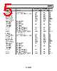


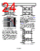


Okay, I've analyzed the text you provided. It appears to be a portion of a datasheet for the ADL5375 device, specifically detailing its performance characteristics at various Local Oscillator (LO) frequencies (3500 MHz, 2600 MHz, 2000 MHz, and 1500 MHz).
Here's a breakdown of what's being presented, along with what I can infer:
Overall Structure:
️· Datasheet Excerpt: This is a snippet from a larger document that provides technical details about the ADL5375.
️· LO Frequency Dependence: The datasheet is showing how the device's performance changes based on the frequency of the LO signal. This is crucial for designing systems using the ADL5375, as different frequencies will affect its operation.
️· Two Versions (ADL5375-05 and ADL5375-15): The datasheet provides data for two versions of the ADL5375, indicated by the suffixes "-05" and "-15". These are likely different manufacturing variants or design versions of the device, which explains the slight differences in the listed values.
Key Parameters Listed (for each LO frequency and device version):
️· Output Power (POUT): The amount of RF power produced by the device, measured in dBm.
️· Modulator Voltage Gain: The amplifier gain.
️· P1dB (1 dB Compression Point): An indication of the output power level where the power starts to compress due to non-linear behavior. It's a measure of the device's dynamic range.
️· Output Return Loss: A measure of how well the output impedance is matched to the load. Lower values are better (less signal reflected).
️· Carrier Feedthrough: The amount of LO signal that leaks into the RF output. Lower values are better.
️· Sideband Suppression: The level of unwanted sidebands produced by the modulator. Lower values are better.
️· Quadrature Error: Indicates the phase difference between the I and Q signals. Smaller values indicate better performance.
️· Second Harmonic: The level of the second harmonic generated by the device, expressed in dBc (decibels relative to the carrier). Lower values are better.
️· Third Harmonic: Similar to the second harmonic, but for the third harmonic. Lower values are better.
️· Noise Figure: A measure of the noise added by the device. Lower values are better.
Key Observations and Possible Inferences:
️· Performance Trend: Generally, as the LO frequency increases, the output power and modulator voltage gain tend to decrease. The other parameters also change, suggesting a frequency-dependent design.
️· Trade-offs: The datasheet suggests that optimizing for one parameter (e.g., higher output power) may negatively affect others (e.g., increased harmonics or higher noise figure).
️· Design Considerations: The data would be used by engineers to select the most appropriate LO frequency for a specific application and to design matching networks to optimize performance.
️· Harmonic Suppression: Keeping harmonic levels low is critical to prevent interference with other parts of a system.
In order to help further, can you please provide the questions you had about this datasheet?
Overall Structure:
️· Datasheet Excerpt: This is a snippet from a larger document that provides technical details about the ADL5375.
️· LO Frequency Dependence: The datasheet is showing how the device's performance changes based on the frequency of the LO signal. This is crucial for designing systems using the ADL5375, as different frequencies will affect its operation.
️· Two Versions (ADL5375-05 and ADL5375-15): The datasheet provides data for two versions of the ADL5375, indicated by the suffixes "-05" and "-15". These are likely different manufacturing variants or design versions of the device, which explains the slight differences in the listed values.
Key Parameters Listed (for each LO frequency and device version):
️· Output Power (POUT): The amount of RF power produced by the device, measured in dBm.
️· Modulator Voltage Gain: The amplifier gain.
️· P1dB (1 dB Compression Point): An indication of the output power level where the power starts to compress due to non-linear behavior. It's a measure of the device's dynamic range.
️· Output Return Loss: A measure of how well the output impedance is matched to the load. Lower values are better (less signal reflected).
️· Carrier Feedthrough: The amount of LO signal that leaks into the RF output. Lower values are better.
️· Sideband Suppression: The level of unwanted sidebands produced by the modulator. Lower values are better.
️· Quadrature Error: Indicates the phase difference between the I and Q signals. Smaller values indicate better performance.
️· Second Harmonic: The level of the second harmonic generated by the device, expressed in dBc (decibels relative to the carrier). Lower values are better.
️· Third Harmonic: Similar to the second harmonic, but for the third harmonic. Lower values are better.
️· Noise Figure: A measure of the noise added by the device. Lower values are better.
Key Observations and Possible Inferences:
️· Performance Trend: Generally, as the LO frequency increases, the output power and modulator voltage gain tend to decrease. The other parameters also change, suggesting a frequency-dependent design.
️· Trade-offs: The datasheet suggests that optimizing for one parameter (e.g., higher output power) may negatively affect others (e.g., increased harmonics or higher noise figure).
️· Design Considerations: The data would be used by engineers to select the most appropriate LO frequency for a specific application and to design matching networks to optimize performance.
️· Harmonic Suppression: Keeping harmonic levels low is critical to prevent interference with other parts of a system.
| Part No. | ADL5387 |
| Manufacturer | AD |
| Size | 2Mb |
| Pages | 32 pages |
| Description | 400 MHz to 6 GHz Broadband Quadrature Modulator |
| ¿ALLDATASHEET es útil para Ud.? [ DONATE ] |
Todo acerca de Alldatasheet | Publicidad | Contáctenos | Política de Privacidad | Enlace a la hoja de datos | Intercambio de Enlaces | Lista de Fabricantes All Rights Reserved©Alldatasheet.com |
| Russian : Alldatasheetru.com | Korean : Alldatasheet.co.kr | Spanish : Alldatasheet.es | French : Alldatasheet.fr | Italian : Alldatasheetit.com Portuguese : Alldatasheetpt.com | Polish : Alldatasheet.pl | Vietnamese : Alldatasheet.vn Indian : Alldatasheet.in | Mexican : Alldatasheet.com.mx | British : Alldatasheet.co.uk | New Zealand : Alldatasheet.co.nz |
|
Family Site : ic2ic.com |
icmetro.com |
 Mexican ▼
  English
 Chinese
 German
 Japanese
 Russian
 Korean
 Spanish
 French
 Italian
 Portuguese
 Polish
 Vietnamese
 Indian
 British
 New Zealand