|
Motor de Búsqueda de Datasheet de Componentes Electrónicos |
|
|
Motor de Búsqueda de Datasheet de Componentes Electrónicos |
|
AD7680 Datasheet(PDF) 13 Page - Analog Devices |
|
|
|||||||||||||||||||||||||||||
AD7680 Datasheet(HTML) 13 Page - Analog Devices |
|
|
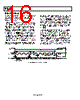
13 / 20 page  AD7940 Rev. 0 | Page 13 of 20 MODES OF OPERATION The mode of operation of the AD7940 is selected by controlling the (logic) state of the CS signal during a conversion. There are two possible modes of operation, normal and power-down. The point at which CS is pulled high after the conversion has been initiated will determine whether or not the AD7940 will enter power-down mode. Similarly, if already in power-down, CS can control whether the device will return to normal operation or remain in power-down. These modes of operation are designed to provide flexible power management options. These options can optimize the power dissipation/throughput rate ratio for differing application requirements. NORMAL MODE This mode provides the fastest throughput rate performance because the user does not have to worry about the power-up times with the AD7940 remaining fully powered all the time. Figure 16 shows the general diagram of the operation of the AD7940 in this mode. The conversion is initiated on the falling edge of CS as described in the Serial Interface section. To ensure that the part remains fully powered up at all times, CS must remain low until at least 10 SCLK falling edges have elapsed after the falling edge of CS. If CS is brought high any time after the 10th SCLK falling edge, but before the 16th SCLK falling edge, the part will remain powered up, but the conversion will be terminated and SDATA will go back into three-state. At least 16 serial clock cycles are required to complete the conversion and access the complete conversion result. CS may idle high until the next conversion or may idle low until CS returns high sometime prior to the next conversion, effectively idling CS low. Once a data transfer is complete (SDATA has returned to three- state), another conversion can be initiated after the quiet time, tQUIET, has elapsed by bringing CS low again. 112 1 LEADING ZERO + CONVERSION RESULT CS SCLK 16 SDATA Figure 16. Normal Mode Operation |
|
|
Enlace URL |
| ¿ALLDATASHEET es útil para Ud.? [ DONATE ] |
Todo acerca de Alldatasheet | Publicidad | Contáctenos | Política de Privacidad | Enlace a la hoja de datos | Intercambio de Enlaces | Lista de Fabricantes All Rights Reserved©Alldatasheet.com |
| Russian : Alldatasheetru.com | Korean : Alldatasheet.co.kr | Spanish : Alldatasheet.es | French : Alldatasheet.fr | Italian : Alldatasheetit.com Portuguese : Alldatasheetpt.com | Polish : Alldatasheet.pl | Vietnamese : Alldatasheet.vn Indian : Alldatasheet.in | Mexican : Alldatasheet.com.mx | British : Alldatasheet.co.uk | New Zealand : Alldatasheet.co.nz |
|
Family Site : ic2ic.com |
icmetro.com |
 Mexican ▼
 English
 Chinese
 German
 Japanese
 Russian
 Korean
 Spanish
 French
 Italian
 Portuguese
 Polish
 Vietnamese
 Indian
 Mexican
 British
 New Zealand