|
Motor de Búsqueda de Datasheet de Componentes Electrónicos |
|
|
Motor de Búsqueda de Datasheet de Componentes Electrónicos |
|
ATS612LSG Datasheet(PDF) 8 Page - Allegro MicroSystems |
|
|
|||||||||||||||||||||||||||||
ATS612LSG Datasheet(HTML) 8 Page - Allegro MicroSystems |
|
|
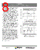
8 / 15 page  ATS612LSG DYNAMIC, SELF-CALIBRATING, PEAK-DETECTING, DIFFERENTIAL HALL-EFFECT GEAR TOOTH SENSOR Page 8 of 15 115 Northeast Cutoff, Box 15036 Worcester, Massachusetts 01615-0036 (508) 853-5000 Copyright © 2001, 2003 Allegro MicroSystems, Inc. • Dual edge detection. Because this device switches from the positive and negative peaks of the signal, dual edge detection is guaranteed. • Tilted or off-center installation. Traditional differential sensors will switch incorrectly due to baseline changes versus air gap caused by tilted or off-center installation. The peak detector circuitry references the switch point from the peak and is immune to this failure mode. There may be a timing accuracy shift caused by this condition. • Large operating air gaps. Large operating air gaps are achievable with this device due to the sensitive switch points after start up. (dependent on target dimensions, material, and speed). • Immunity to magnetic overshoot. The air gap- independent hysteresis minimizes the impact of overshoot on the switching of device output. • Response to surface defects in the target. The gain-adjust circuitry reduces the effect of minor gear anomalies that would normally cause false switching. • Immunity to vibration and backlash. The gain- adjust circuitry keeps the hysteresis of the device roughly proportional to the peak-to-peak signal. This allows the device to have good immunity to vibration even when operating at close air gaps. • Immunity to gear run out. The differential sensor configuration eliminates the baseline variations caused by gear run out. Differential vs. Single-Element Sensing. The differential Hall-effect configuration is superior in most applications to the classical single-element gear-tooth sensor. As shown in the flux maps on th is page, the single-element configuration commonly used (Hall-effect sensor mounted on the face of a simple permanent magnet) requires the detection of a small signal (often <100 G) that is superimposed on a large back-biased field, often 1500 G to 3500 G. For most gear/target configurations, the back-biased field values change due to concentration effects, resulting in a varying baseline with air gap, with valley widths, with eccentricities, and with vibration. The differential configuration cancels the effects of the back-biased field and avoids many of the issues presented by the single Hall element. NOTE: 10 G = 1 mT, exactly. |
|
|
Enlace URL |
| ¿ALLDATASHEET es útil para Ud.? [ DONATE ] |
Todo acerca de Alldatasheet | Publicidad | Contáctenos | Política de Privacidad | Enlace a la hoja de datos | Intercambio de Enlaces | Lista de Fabricantes All Rights Reserved©Alldatasheet.com |
| Russian : Alldatasheetru.com | Korean : Alldatasheet.co.kr | Spanish : Alldatasheet.es | French : Alldatasheet.fr | Italian : Alldatasheetit.com Portuguese : Alldatasheetpt.com | Polish : Alldatasheet.pl | Vietnamese : Alldatasheet.vn Indian : Alldatasheet.in | Mexican : Alldatasheet.com.mx | British : Alldatasheet.co.uk | New Zealand : Alldatasheet.co.nz |
|
Family Site : ic2ic.com |
icmetro.com |
 Mexican ▼
 English
 Chinese
 German
 Japanese
 Russian
 Korean
 Spanish
 French
 Italian
 Portuguese
 Polish
 Vietnamese
 Indian
 Mexican
 British
 New Zealand