 |
Motor de Búsqueda de Datasheet de Componentes Electrónicos |
|
|
Motor de Búsqueda de Datasheet de Componentes Electrónicos |
|
MAX17841BGUE Datasheet(PDF) 9 Page - Maxim Integrated Products |
|
|
|||||||||||||||||||||||||||||
MAX17841BGUE Datasheet(HTML) 9 Page - Maxim Integrated Products |
|
|
9 / 33 page 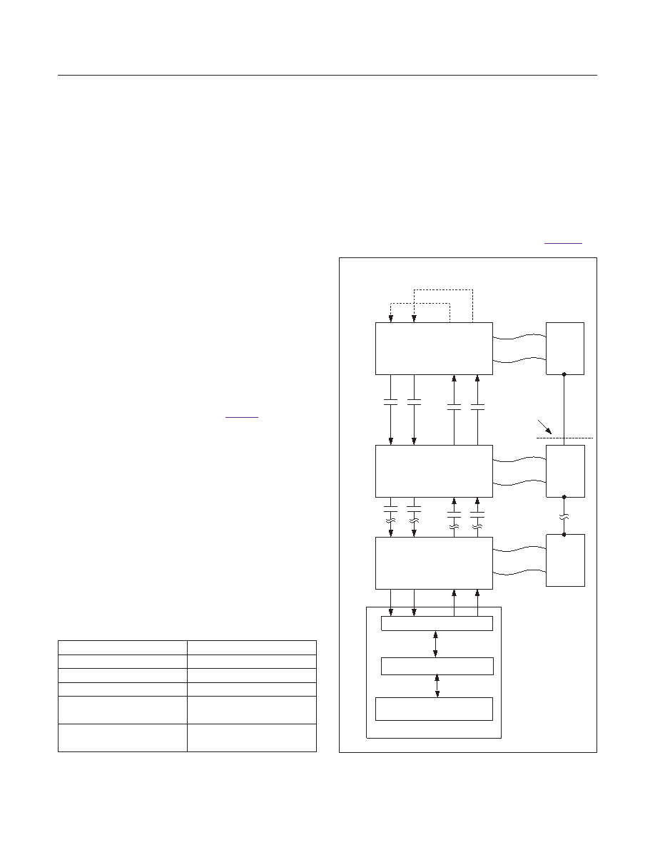 nate the transaction (single-byte transaction), continue to clock data out (write transaction), or start clocking data in (readtransaction).However,itdoesnotsendandreceive data at the same time (half-duplex operation). Register Transactions For register transactions, the host first sends a single-byte register address. Register addresses are either read-only (odd addresses) or write-only (even addresses). For a read transaction, the second byte is the read data sent by the ASCI to the host. For a write transaction, the second byte is the write data sent by the host to the ASCI. Multiple data bytes are allowed as long as CS remains active- low—the ASCI automatically selects the next read-only register address (for reads) or the next write-only address (for writes). The SPI transaction is terminated when the host drives CS high. Buffer Transactions Buffer transactions can consist of only a command byte, a command byte followed by one or more read bytes, or a command byte followed by one or more write bytes. All allowed transactions are specified in Table 9. SPI Timing TheASCIisonlycompatiblewithSPImode0(CPOL= 0/CPHA=0).Inthismode,dataisalwaysdrivenonthe fallingedgeofSCLKandisalwayssampledontherising edgeofSCLK. Forreads,theASCIstartsdrivingDOUTonthefirstfall- ing edge of SCLK immediately after theASCI samples the least-significant bit (LSB) of the command/address byte.DINisa“don’tcare”whilereading.Readsattempted beyondtheaddressspacereturnzero. For writes, registers are written on the falling edge of SCLK,afterthelastbitissampled.However,ifCS goes highbeforethelastbit’sfallingedgeofSCLK,thatregister is not written. UART Interface Slave devices that use Maxim’s battery management UART protocol can be connected in daisy-chain fashion to manage a multiple battery-cell stack. In a BMS, or Battery Management System, the BMS controller is the host for all slave devices and initiates all communication. The data flow always starts from the host, goes up the daisy-chain and back down to the host as represented in Figure 6. Table 2. SPI Communication Summary Figure 6. System Data Flow PARAMETER VALUE Communication Mode Half-duplex Maximum Clock Frequency 4MHz BitOrder Most-significantbitfirst ClockPolarity(CPOL) 0 (leading clock edge is rising edge) ClockPhase(CPHA) 0 (data sampled on leading clock edge) CHOOSE INTERNAL OR EXTERNAL LOOPBACK RXUP RXUN TXUP TXUN TXLP TXLN RXLP RXLN DEVICE (n) RXUP RXUN TXUP TXUN TXLP TXLN RXLP RXLN DEVICE (n-1) RXUP RXUN TXUP TXUN TXLP TXLN RXLP RXLN DEVICE 1 BMS ISOLATION MAX17841B µC BATTERY PACK n BATTERY PACK (n - 1) BATTERY PACK 1 OPTIONAL SERVICE DISCONNECT Maxim Integrated │ 9 MAX17841B Automotive SPI Communication Interface (ASCI) www.maximintegrated.com |
|
Enlace URL |
| ¿ALLDATASHEET es útil para Ud.? [ DONATE ] |
Todo acerca de Alldatasheet | Publicidad | Contáctenos | Política de Privacidad | Enlace a la hoja de datos | Intercambio de Enlaces | Lista de Fabricantes All Rights Reserved©Alldatasheet.com |
| Russian : Alldatasheetru.com | Korean : Alldatasheet.co.kr | Spanish : Alldatasheet.es | French : Alldatasheet.fr | Italian : Alldatasheetit.com Portuguese : Alldatasheetpt.com | Polish : Alldatasheet.pl | Vietnamese : Alldatasheet.vn Indian : Alldatasheet.in | Mexican : Alldatasheet.com.mx | British : Alldatasheet.co.uk | New Zealand : Alldatasheet.co.nz |
|
Family Site : ic2ic.com |
icmetro.com |
 Mexican ▼
 English
 Chinese
 German
 Japanese
 Russian
 Korean
 Spanish
 French
 Italian
 Portuguese
 Polish
 Vietnamese
 Indian
 Mexican
 British
 New Zealand


