 |
Motor de Búsqueda de Datasheet de Componentes Electrónicos |
|
|
Motor de Búsqueda de Datasheet de Componentes Electrónicos |
|
RXM-GPS-R4-X Datasheet(PDF) 6 Page - Linx Technologies |
|
|
|||||||||||||||||||||||||||||
RXM-GPS-R4-X Datasheet(HTML) 6 Page - Linx Technologies |
|
|
6 / 9 page 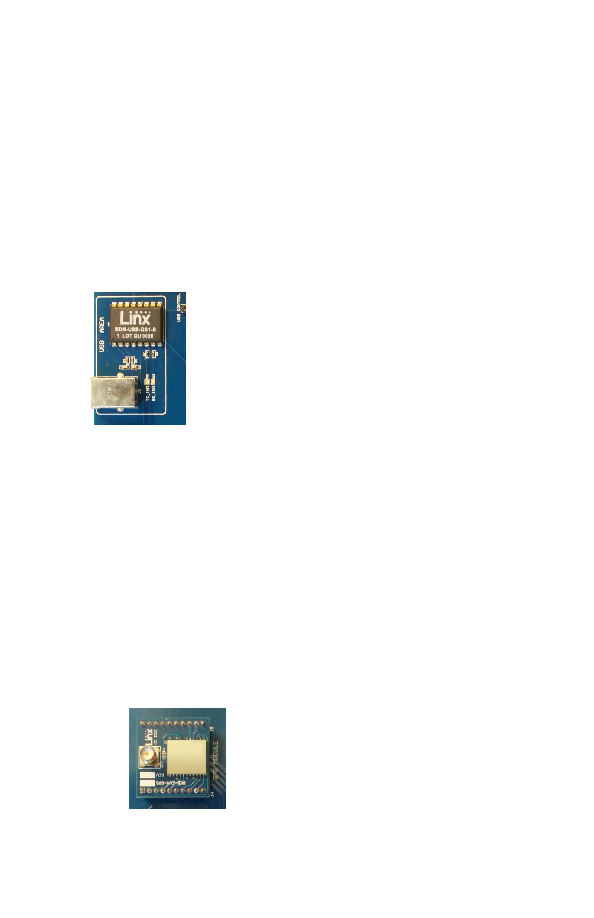 – – – – 6 7 The USB Section The development board features a Linx QS Series USB module for interface to a PC. This allows the board to be used with the supplied development software or with custom software developed by the user. Drivers for the USB module are included on the software CD in the kit or may be downloaded from www.linxtechnologies.com. Additional information on using the QS Series USB module can also be found on the website. The USB connection also allows the board to be powered by the USB bus instead of batteries. This can be convenient during development to eliminate the need for frequent battery replacement. Figure 6: The Development Board USB Section The Receiver Section The receiver module is mounted on an evaluation board which plugs into headers on the main development board. The evaluation board has an SMA antenna connector to allow the attachment of many different styles of GPS antennas, including the included SH Series active GPS antenna. Each receiver module has its own evaluation board, but all of them are designed to fit into the same socket on the main board. On the bottom of the main board is a CR2032 coin cell battery that provides power to the Real Time Clock (RTC) and SRAM when the receiver is powered down. This allows the receiver to start up and obtain a position fix faster. This cell provides about two years of operation. Figure 5: The Development Board Receiver Section |
|
|
Enlace URL |
| ¿ALLDATASHEET es útil para Ud.? [ DONATE ] |
Todo acerca de Alldatasheet | Publicidad | Contáctenos | Política de Privacidad | Enlace a la hoja de datos | Intercambio de Enlaces | Lista de Fabricantes All Rights Reserved©Alldatasheet.com |
| Russian : Alldatasheetru.com | Korean : Alldatasheet.co.kr | Spanish : Alldatasheet.es | French : Alldatasheet.fr | Italian : Alldatasheetit.com Portuguese : Alldatasheetpt.com | Polish : Alldatasheet.pl | Vietnamese : Alldatasheet.vn Indian : Alldatasheet.in | Mexican : Alldatasheet.com.mx | British : Alldatasheet.co.uk | New Zealand : Alldatasheet.co.nz |
|
Family Site : ic2ic.com |
icmetro.com |
 Mexican ▼
 English
 Chinese
 German
 Japanese
 Russian
 Korean
 Spanish
 French
 Italian
 Portuguese
 Polish
 Vietnamese
 Indian
 Mexican
 British
 New Zealand


