 |
Motor de Búsqueda de Datasheet de Componentes Electrónicos |
|
|
Motor de Búsqueda de Datasheet de Componentes Electrónicos |
|
MPZ2012S221A Datasheet(PDF) 27 Page - STMicroelectronics |
|
|
|||||||||||||||||||||||||||||
MPZ2012S221A Datasheet(HTML) 27 Page - STMicroelectronics |
|
|
27 / 56 page 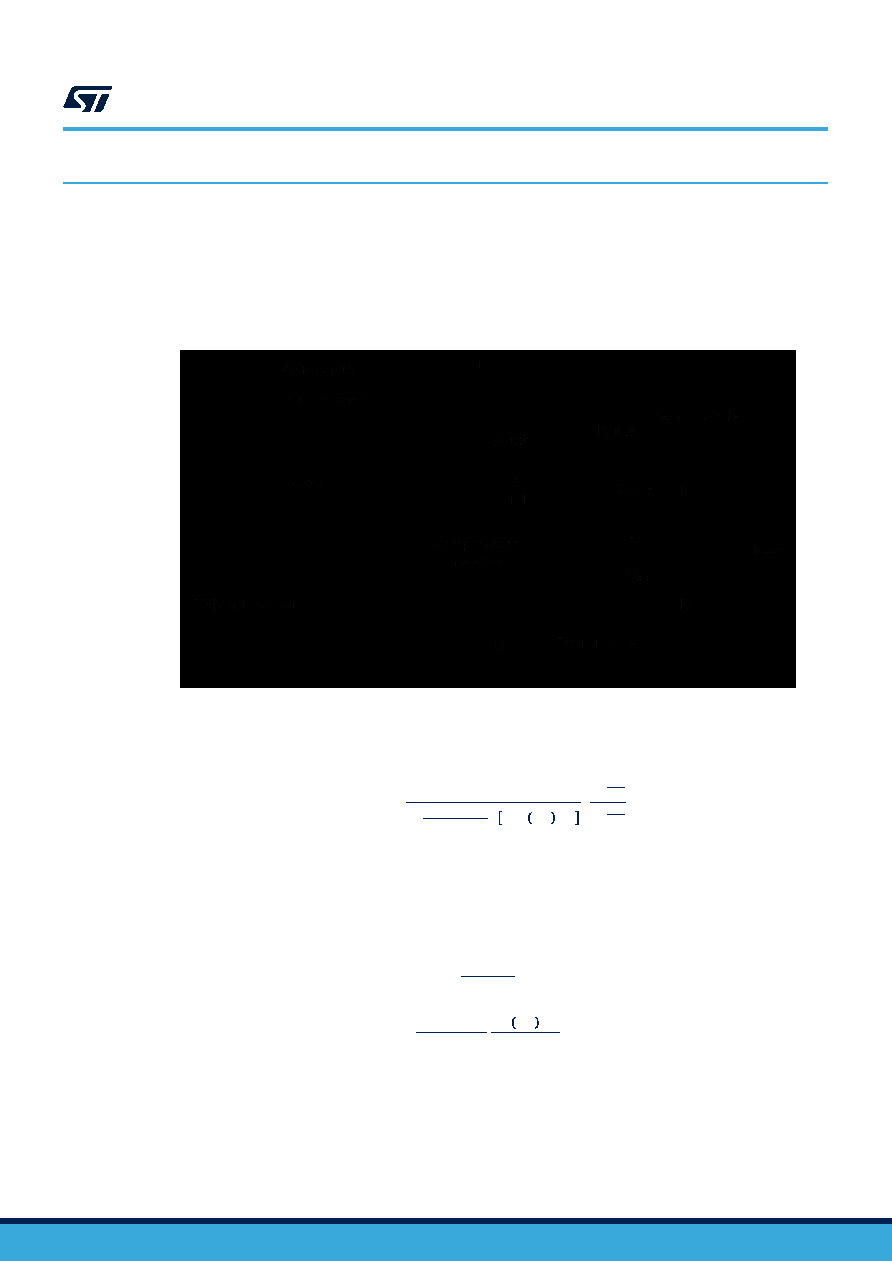 8 Closing the loop The iso-buck, compared to a standard buck, includes the transformer in place of the inductor and all the components connected to the secondary winding (at least the Schottky diode and the secondary output capacitor). Nevertheless, the regulation loop does not include the secondary side components. As a first approximation the control loop of an iso-buck can be assimilated to the one of a standard buck. Therefore, the block diagram in the figure below can still be used (where the inductor symbol identifies the inductance of the primary winding) as well as all the equations and calculations in the next sections. Figure 34. Block diagram of the loop 8.1 GCO(s)control to output transfer function The accurate control to output transfer function for a buck peak current mode converter can be written as: GCO(s)=RLOAD⋅gCS⋅ 1 1+RLOAD∙TSW L ⋅ mC⋅ 1‐D‐0.5 ⋅ 1+sωZ1+sωp⋅FH(s) (5) where RLOAD represents the load resistance, gCS the equivalent sensing transconductance of the current sense circuitry, wp the single pole introduced by the power stage and wz the zero given by the ESR of the output capacitor. FH(s) accounts the sampling effect performed by the PWM comparator on the output of the error amplifier that introduces a double pole at one half of the switching frequency. ωZ= 1ESR∙COUT (6) ωp= 1 RLOAD∙COUT∙mC∙1‐D‐0.5 L∙COUT∙fSW (7) where: L6983I Closing the loop DS14040 - Rev 1 page 27/56 |
|
Enlace URL |
| ¿ALLDATASHEET es útil para Ud.? [ DONATE ] |
Todo acerca de Alldatasheet | Publicidad | Contáctenos | Política de Privacidad | Enlace a la hoja de datos | Intercambio de Enlaces | Lista de Fabricantes All Rights Reserved©Alldatasheet.com |
| Russian : Alldatasheetru.com | Korean : Alldatasheet.co.kr | Spanish : Alldatasheet.es | French : Alldatasheet.fr | Italian : Alldatasheetit.com Portuguese : Alldatasheetpt.com | Polish : Alldatasheet.pl | Vietnamese : Alldatasheet.vn Indian : Alldatasheet.in | Mexican : Alldatasheet.com.mx | British : Alldatasheet.co.uk | New Zealand : Alldatasheet.co.nz |
|
Family Site : ic2ic.com |
icmetro.com |
 Mexican ▼
 English
 Chinese
 German
 Japanese
 Russian
 Korean
 Spanish
 French
 Italian
 Portuguese
 Polish
 Vietnamese
 Indian
 Mexican
 British
 New Zealand


