 |
Motor de Búsqueda de Datasheet de Componentes Electrónicos |
|
|
Motor de Búsqueda de Datasheet de Componentes Electrónicos |
|
ADL8121ACPZN-R7 Datasheet(PDF) 21 Page - Analog Devices |
|
|
|||||||||||||||||||||||||||||
ADL8121ACPZN-R7 Datasheet(HTML) 21 Page - Analog Devices |
|
|
21 / 22 page 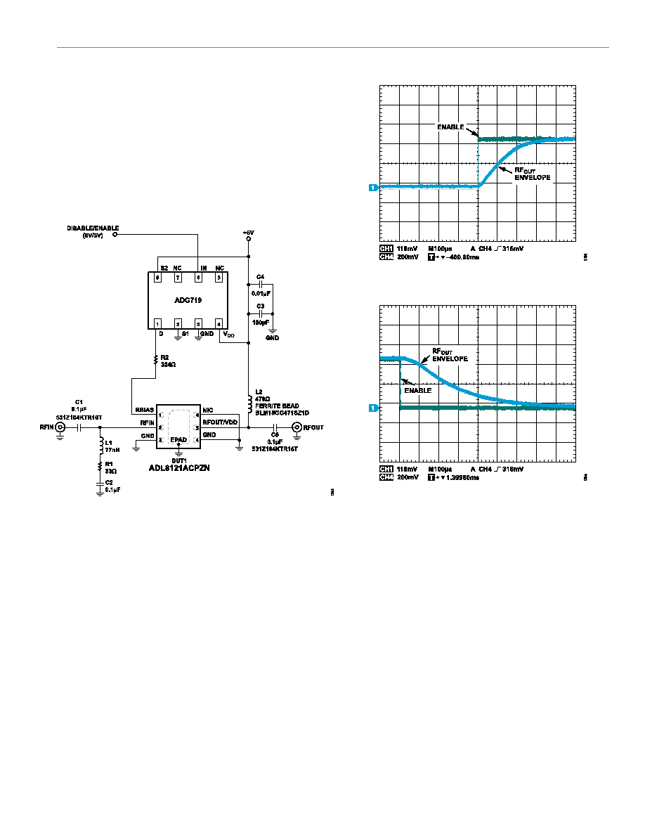 Data Sheet ADL8121 USING RBIAS TO ENABLE AND DISABLE ADL8121 analog.com Rev. A | 21 of 22 By attaching a single-pole, double throw (SPDT) switch to the RBIAS pin, an enable and disable circuit can be implemented as shown in Figure 80. The ADG719 CMOS switch is used to connect the RBIAS resistor either to supply or ground. When the RBIAS resistor is connected to ground, the overall current consumption reduces to 1.0 mA with no RF signal present and 4.0 mA when the RF input level is –10 dBm. Figure 81 and Figure 82 show plots of the turn on and the turn off response time of the RF output envelope when the IN pin of the ADG719 is pulsed. Figure 80. Fast Enable and Disable Using a 0 V to 5 V Pulse on the RBIAS Resistor Figure 81. Turn-On Response Time of the RF Output (RFOUT) Envelope When IN Pin of the ADG719 Is Pulsed Figure 82. Turn-Off Response Time of the RFOUT Envelope When IN Pin of the ADG719 Is Pulsed |
|
|
Enlace URL |
| ¿ALLDATASHEET es útil para Ud.? [ DONATE ] |
Todo acerca de Alldatasheet | Publicidad | Contáctenos | Política de Privacidad | Enlace a la hoja de datos | Intercambio de Enlaces | Lista de Fabricantes All Rights Reserved©Alldatasheet.com |
| Russian : Alldatasheetru.com | Korean : Alldatasheet.co.kr | Spanish : Alldatasheet.es | French : Alldatasheet.fr | Italian : Alldatasheetit.com Portuguese : Alldatasheetpt.com | Polish : Alldatasheet.pl | Vietnamese : Alldatasheet.vn Indian : Alldatasheet.in | Mexican : Alldatasheet.com.mx | British : Alldatasheet.co.uk | New Zealand : Alldatasheet.co.nz |
|
Family Site : ic2ic.com |
icmetro.com |
 Mexican ▼
 English
 Chinese
 German
 Japanese
 Russian
 Korean
 Spanish
 French
 Italian
 Portuguese
 Polish
 Vietnamese
 Indian
 Mexican
 British
 New Zealand


