 |
Motor de Búsqueda de Datasheet de Componentes Electrónicos |
|
|
Motor de Búsqueda de Datasheet de Componentes Electrónicos |
|
STDS75 Datasheet(PDF) 21 Page - STMicroelectronics |
|
|
|||||||||||||||||||||||||||||
STDS75 Datasheet(HTML) 21 Page - STMicroelectronics |
|
|
21 / 37 page 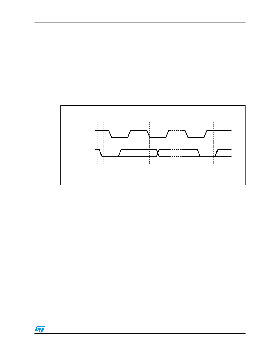 STDS75 Functional description 21/37 3.4.4 Data valid The state of the data line represents valid data when after a start condition, the data line is stable for the duration of the high period of the clock signal. The data on the line may be changed during the Low period of the clock signal. There is one clock pulse per bit of data. Each data transfer is initiated with a start condition and terminated with a stop condition. The number of data bytes transferred between the start and stop conditions is not limited. The information is transmitted byte-wide and each receiver acknowledges with a ninth bit. By definition a device that gives out a message is called “transmitter,” the receiving device that gets the message is called “receiver.” The device that controls the message is called “master.” The devices that are controlled by the master are called “slaves.” Figure 6. Serial bus data transfer sequence AI00587 DATA CLOCK DATA LINE STABLE DATA VALID START CONDITION CHANGE OF DATA ALLOWED STOP CONDITION |
|
Enlace URL |
| ¿ALLDATASHEET es útil para Ud.? [ DONATE ] |
Todo acerca de Alldatasheet | Publicidad | Contáctenos | Política de Privacidad | Enlace a la hoja de datos | Intercambio de Enlaces | Lista de Fabricantes All Rights Reserved©Alldatasheet.com |
| Russian : Alldatasheetru.com | Korean : Alldatasheet.co.kr | Spanish : Alldatasheet.es | French : Alldatasheet.fr | Italian : Alldatasheetit.com Portuguese : Alldatasheetpt.com | Polish : Alldatasheet.pl | Vietnamese : Alldatasheet.vn Indian : Alldatasheet.in | Mexican : Alldatasheet.com.mx | British : Alldatasheet.co.uk | New Zealand : Alldatasheet.co.nz |
|
Family Site : ic2ic.com |
icmetro.com |
 Mexican ▼
 English
 Chinese
 German
 Japanese
 Russian
 Korean
 Spanish
 French
 Italian
 Portuguese
 Polish
 Vietnamese
 Indian
 Mexican
 British
 New Zealand


