 |
Motor de Búsqueda de Datasheet de Componentes Electrónicos |
|
|
Motor de Búsqueda de Datasheet de Componentes Electrónicos |
|
ADL5385ACPZ-R7 Datasheet(PDF) 15 Page - Analog Devices |
|
|
|||||||||||||||||||||||||||||
ADL5385ACPZ-R7 Datasheet(HTML) 15 Page - Analog Devices |
|
|
15 / 24 page 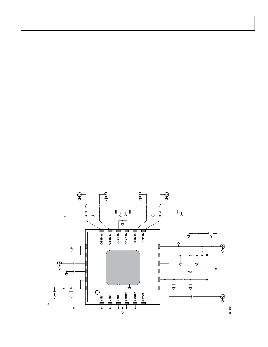 Data Sheet ADL5385 Rev. D | Page 15 of 24 BASIC CONNECTIONS Figure 29 shows the basic connections for the ADL5385. POWER SUPPLY AND GROUNDING All the VPS pins must be connected to the same 5 V source. Adjacent pins of the same name can be tied together and decoupled with a 0.1 µF capacitor. Locate these capacitors as close as possible to the device. The power supply can range from 4.75 V to 5.5 V. The COM1 pin, COM2 pin, and COM3 pin are tied to the same ground plane through low impedance paths. The exposed pad on the underside of the package is also soldered to a low thermal and electrical impedance ground plane. If the ground plane spans multiple layers on the circuit board, stitch the layers together with nine vias under the exposed pad. The Analog Devices AN-722 Application Note discusses the thermal and electrical grounding of the LFCSP in greater detail. BASEBAND INPUTS The baseband inputs QBBP, QBBN, IBBP, and IBBN must be driven from a differential source. The nominal drive level of 1.4 V p-p differential (700 mV p-p on each pin) is biased to a common-mode level of 500 mV dc. The dc common-mode bias level for the baseband inputs can range from 400 mV to 600 mV. This results in a reduction in the usable input ac swing range. The nominal dc bias of 500 mV allows for the largest ac swing, limited on the bottom end by the ADL5385 input range and on the top end by the output compliance range on most Analog Devices DACs. LO INPUT A single-ended LO signal is applied to the LOIP pin through an ac coupling capacitor. The LO return pin, LOIN, must be ac-coupled to ground though a low impedance path. The LO input can be driven differentially, in which case the user ac couples both sides of the differential LO source through a pair of series capacitors to the LOIP and LOIN pins. The nominal LO drive of −7 dBm, which is recommended, can be increased to up to 5 dBm. For operation below 50 MHz, it is recommended to use a minimum LO drive level of 0 dBm. The effect of LO power on sideband suppression and carrier feedthrough is shown in Figure 17 and Figure 21. The performance vs. LO power at 30 MHz output frequency is shown at Figure 9. RF OUTPUT The RF output is available at the VOUT pin (Pin 7). This pin must also be ac-coupled. Below 150 MHz, output power decreases due to internal ac-coupling. This is shown in Figure 8. The VOUT pin has a nominal broadband impedance of 50 Ω and does not need further external matching. R22 10k Ω VPOS GND VPOS VPOS SW21 R21 49.9 Ω OFF ON LO VOUT ENBL RFPQ 0 Ω RFNQ 0 Ω CFPQ OPEN CFNQ OPEN QBBP QBBN 24 VPS3 23 VPS3 22 LOIN 21 LOIP 20 COM3 19 COM3 VOUT 7 VPS1 8 VPS1 9 TEMP 10 VPS2 11 ENBL 12 ADL5385 U1 4 × 4 LFCSP EXPOSED PADDLE TEMP ENB RTQ OPEN R11 0 Ω RFNI 0 Ω RFPI 0 Ω CFNI OPEN CFPI OPEN IBBN IBBP RTI OPEN CLOP 0.1µF CLON 0.1µF C11 OPEN C12 0.1µF R12 0 Ω RTEMP 200 Ω C14 0.1µF C13 OPEN C16 0.1µF C15 OPEN COUT 0.1µF R13 0 Ω Figure 29. Basic Connections for the ADL5385 |
|
|
Enlace URL |
| ¿ALLDATASHEET es útil para Ud.? [ DONATE ] |
Todo acerca de Alldatasheet | Publicidad | Contáctenos | Política de Privacidad | Enlace a la hoja de datos | Intercambio de Enlaces | Lista de Fabricantes All Rights Reserved©Alldatasheet.com |
| Russian : Alldatasheetru.com | Korean : Alldatasheet.co.kr | Spanish : Alldatasheet.es | French : Alldatasheet.fr | Italian : Alldatasheetit.com Portuguese : Alldatasheetpt.com | Polish : Alldatasheet.pl | Vietnamese : Alldatasheet.vn Indian : Alldatasheet.in | Mexican : Alldatasheet.com.mx | British : Alldatasheet.co.uk | New Zealand : Alldatasheet.co.nz |
|
Family Site : ic2ic.com |
icmetro.com |
 Mexican ▼
 English
 Chinese
 German
 Japanese
 Russian
 Korean
 Spanish
 French
 Italian
 Portuguese
 Polish
 Vietnamese
 Indian
 Mexican
 British
 New Zealand


