|
Motor de Búsqueda de Datasheet de Componentes Electrónicos |
|
|
Motor de Búsqueda de Datasheet de Componentes Electrónicos |
|
ACT8325 Datasheet(PDF) 4 Page - Active-Semi, Inc |
|
|
|||||||||||||||||||||||||||||
ACT8325 Datasheet(HTML) 4 Page - Active-Semi, Inc |
|
|
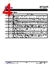
4 / 11 page  ACT8325 Rev 2, 25-May-11 Active-Semi Innovative Power TM - 4 - www.active-semi.com Copyright © 2011 Active-Semi, Inc. ActivePMU TM is a trademark of Active-Semi. PIN DESCRIPTIONS PIN NAME DESCRIPTION 1 VP1 Power Input for REG1. Bypass to GP12 with a high quality ceramic capacitor placed as close as possible to the IC. 2 SW1 Switching Node Output for REG1. Connect this pin to the switching end of the inductor. 3 GP12 Power Ground for REG1, REG2. Connect GA and GP12 together at single point as close to the IC as possible. 4 SW2 Switching Node Output for REG2. Connect this pin to the switching end of the inductor. 5 VP2 Power Input for REG2. Bypass to GP12 with a high quality ceramic capacitor placed as close as possible to the IC. 6 FB2 Feedback Node for REG2. For fixed output voltage options, connect this pin directly to the out- put. For the adjustable output voltage options the voltage at this pin is regulated to 0.625V, con- nect this pin to the center of the output feedback resistor divider for voltage setting. 7 GA Analog Ground. Connect GA directly to a quiet ground node. Connect GA and GP12 together at a single point as close to the IC as possible. 8 ON1 Enable Control Input for REG1. Drive ON1 to VP1 or to a logic high for normal operation, drive to GA or to a logic low to disable REG1. 9 ON2 Enable Control Input for REG2. Drive ON2 to VP1or to a logic high for normal operation, drive to GA or to a logic low to disable REG2. 10 FB1 Feedback Node for REG1. For fixed output voltage options, connect this pin directly to the out- put. For the adjustable output voltage options the voltage at this pin is regulated to 0.625V, con- nect this pin to the center of the output feedback resistor divider for voltage setting. EP EP Exposed Pad. Must be soldered to ground on PCB. |
|
|
Enlace URL |
| ¿ALLDATASHEET es útil para Ud.? [ DONATE ] |
Todo acerca de Alldatasheet | Publicidad | Contáctenos | Política de Privacidad | Enlace a la hoja de datos | Intercambio de Enlaces | Lista de Fabricantes All Rights Reserved©Alldatasheet.com |
| Russian : Alldatasheetru.com | Korean : Alldatasheet.co.kr | Spanish : Alldatasheet.es | French : Alldatasheet.fr | Italian : Alldatasheetit.com Portuguese : Alldatasheetpt.com | Polish : Alldatasheet.pl | Vietnamese : Alldatasheet.vn Indian : Alldatasheet.in | Mexican : Alldatasheet.com.mx | British : Alldatasheet.co.uk | New Zealand : Alldatasheet.co.nz |
|
Family Site : ic2ic.com |
icmetro.com |
 Mexican ▼
 English
 Chinese
 German
 Japanese
 Russian
 Korean
 Spanish
 French
 Italian
 Portuguese
 Polish
 Vietnamese
 Indian
 Mexican
 British
 New Zealand