|
Motor de Búsqueda de Datasheet de Componentes Electrónicos |
|
|
Motor de Búsqueda de Datasheet de Componentes Electrónicos |
|
MS6894 Datasheet(PDF) 6 Page - MOSA ELECTRONICS |
|
|
|||||||||||||||||||||||||||||
MS6894 Datasheet(HTML) 6 Page - MOSA ELECTRONICS |
|
|
6 / 9 page 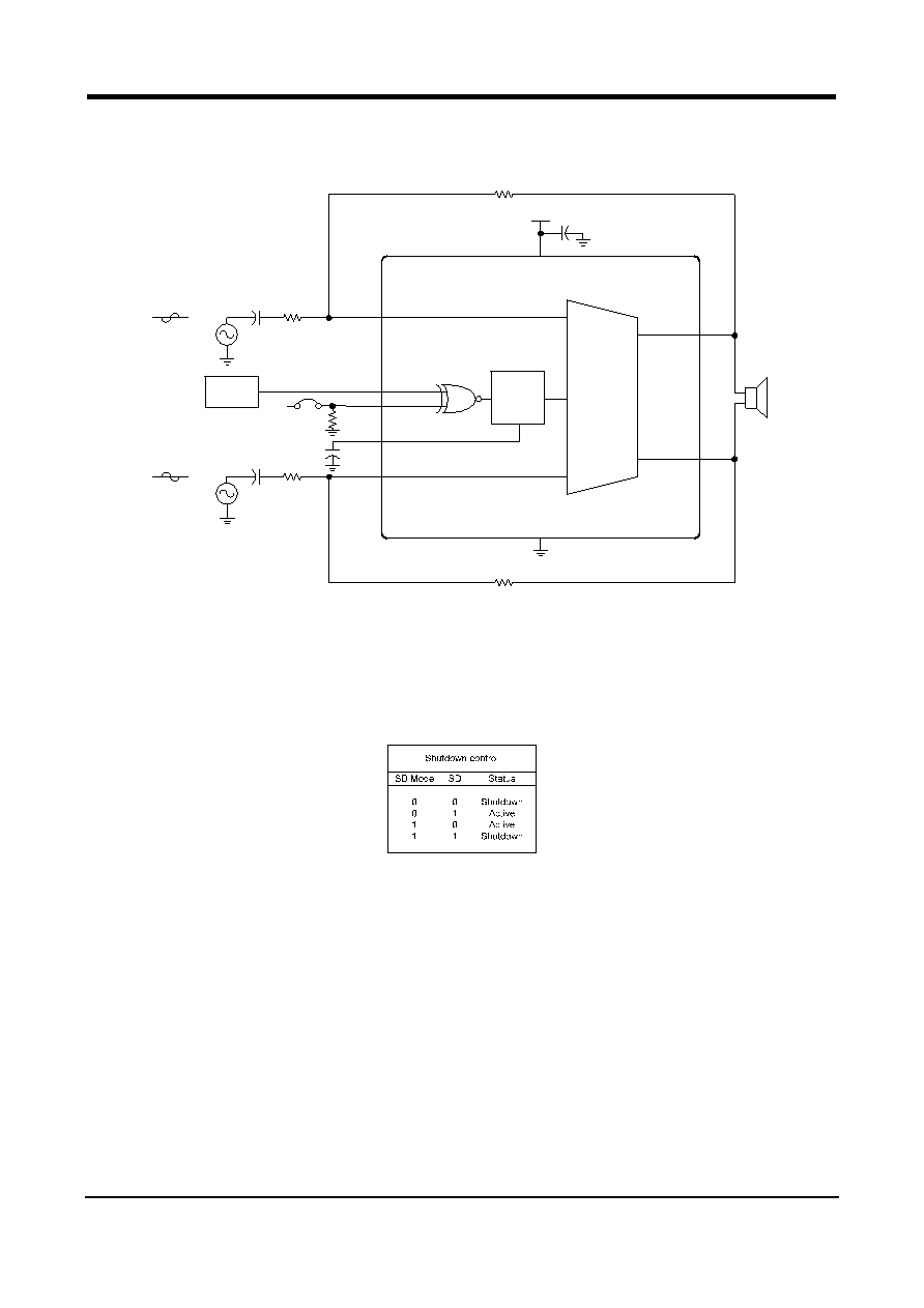 MOSA MS6894 Mono 1.1W Fully Differential Power Amplifier with Shutdown Selection REV 1 6/9 www.mosanalog.com APPLICATION INFORMATION Basic application example 2 R L 8Ω 5 3 4 SD Mode -IN BP SD + +IN Bias V DD GND 1 7 6 10 + - - + Common mode 9 1uF 100k 1uF 20k R F1 V DD 20k R F2 - 0.39uF 20k R I1 MCU V DD 0.39uF 20k + Differential Input R I2 Vo2 Vo1 - Differential Input Fig.1 A audio amplifier application circuit. Shutdown Control The shutdown may be enabled by either logic high or logic low that depending on shutdown mode selection. Both the SD pin and the SD Mode pin are TTL compatible input. The SD Mode is logic low, the device entries shutdown when SD is logic low. The SD Mode is logic high, the device entries shutdown when SD is logic high. External gain-setting As shown in Fig.1, RI1 =RI2 and RF1 =RF2, the respective closed-loop gain is set at -RF/RI. It is important to match input resistors and feedback resistors to each other. The outputs are used to drive the mono bridged-tied load (BTL). High Pass Filter The input capacitor CIN and resister RIN are decided the cut-off frequency of the HPF. The equation is as follows: fcut-off = 1 / (2π*RIN *CIN) Thermal pad considerations The thermal pad must be connected to ground. The package with thermal pad of the MS6894 requires special attention on thermal design. The thermal pad on the bottom of the MS6894 should be soldered down to a copper pad on the circuit board. Heat can be conducted away from the thermal pad through the copper plane to ambient. If the copper plane is not on the top surface of the circuit board, 9 vias of 13 mil or smaller in diameter should be used to thermally couple the thermal pad to the bottom plane. For good thermal conduction, the vias must be plated through and solder filled. |
|
|
Enlace URL |
| ¿ALLDATASHEET es útil para Ud.? [ DONATE ] |
Todo acerca de Alldatasheet | Publicidad | Contáctenos | Política de Privacidad | Enlace a la hoja de datos | Intercambio de Enlaces | Lista de Fabricantes All Rights Reserved©Alldatasheet.com |
| Russian : Alldatasheetru.com | Korean : Alldatasheet.co.kr | Spanish : Alldatasheet.es | French : Alldatasheet.fr | Italian : Alldatasheetit.com Portuguese : Alldatasheetpt.com | Polish : Alldatasheet.pl | Vietnamese : Alldatasheet.vn Indian : Alldatasheet.in | Mexican : Alldatasheet.com.mx | British : Alldatasheet.co.uk | New Zealand : Alldatasheet.co.nz |
|
Family Site : ic2ic.com |
icmetro.com |
 Mexican ▼
 English
 Chinese
 German
 Japanese
 Russian
 Korean
 Spanish
 French
 Italian
 Portuguese
 Polish
 Vietnamese
 Indian
 Mexican
 British
 New Zealand