|
Motor de Búsqueda de Datasheet de Componentes Electrónicos |
|
|
Motor de Búsqueda de Datasheet de Componentes Electrónicos |
|
STM32F373C8 Datasheet(PDF) 14 Page - STMicroelectronics |
|
|
|||||||||||||||||||||||||||||
STM32F373C8 Datasheet(HTML) 14 Page - STMicroelectronics |
|
|
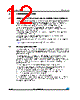
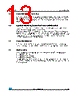
14 / 128 page  Functional overview STM32F37x 14/128 Doc ID 022691 Rev 3 3.7 Power management 3.7.1 Power supply schemes ● VDD: external power supply for I/Os and the internal regulator. It is provided externally through VDD pins, and can be 2.0 to 3.6 V. ● VDDA = 2.0 to 3.6 V: – external analog power supplies for Reset blocks, RCs and PLL – supply voltage for 12-bit ADC, DACs and comparators (minimum voltage to be applied to VDDA is 2.4 V when the 12-bit ADC and DAC are used). ● VDDSD12 and VDDSD3 = 2.2 to 3.6 V: supply voltages for SDADC1/2 and SDADCD3 sigma delta ADCs. Independent from VDD/VDDA. ● VBAT = 1.65 to 3.6 V: power supply for RTC, external clock 32 kHz oscillator and backup registers when VDD is not present. 3.7.2 Power supply supervisor ● The device has an integrated power-on reset (POR)/power-down reset (PDR) circuitry. It is always active, and ensures proper operation starting from/down to 2 V. The device remains in reset mode when VDD is below a specified threshold, VPOR/PDR, without the need for an external reset circuit. The POR monitors only the VDD supply voltage. During the startup phase it is required that VDDA should arrive first and be greater than or equal to VDD. ● The PDR monitors both the VDD and VDDA supply voltages, however the VDDA power supply supervisor can be disabled (by programming a dedicated Option bit) to reduce the power consumption if the application design ensures that VDDA is higher than or equal to VDD. The device features an embedded programmable voltage detector (PVD) that monitors the VDD power supply and compares it to the VPVD threshold. An interrupt can be generated when VDD drops below the VPVD threshold and/or when VDD is higher than the VPVD threshold. The interrupt service routine can then generate a warning message and/or put the MCU into a safe state. The PVD is enabled by software. 3.7.3 Voltage regulator The regulator has three operation modes: main (MR), low power (LPR), and power-down. ● The MR mode is used in the nominal regulation mode (Run) ● The LPR mode is used in Stop mode. ● The power-down mode is used in Standby mode: the regulator output is in high impedance, and the kernel circuitry is powered down thus inducing zero consumption. The voltage regulator is always enabled after reset. It is disabled in Standby mode. |
|
Enlace URL |
| ¿ALLDATASHEET es útil para Ud.? [ DONATE ] |
Todo acerca de Alldatasheet | Publicidad | Contáctenos | Política de Privacidad | Enlace a la hoja de datos | Intercambio de Enlaces | Lista de Fabricantes All Rights Reserved©Alldatasheet.com |
| Russian : Alldatasheetru.com | Korean : Alldatasheet.co.kr | Spanish : Alldatasheet.es | French : Alldatasheet.fr | Italian : Alldatasheetit.com Portuguese : Alldatasheetpt.com | Polish : Alldatasheet.pl | Vietnamese : Alldatasheet.vn Indian : Alldatasheet.in | Mexican : Alldatasheet.com.mx | British : Alldatasheet.co.uk | New Zealand : Alldatasheet.co.nz |
|
Family Site : ic2ic.com |
icmetro.com |
 Mexican ▼
 English
 Chinese
 German
 Japanese
 Russian
 Korean
 Spanish
 French
 Italian
 Portuguese
 Polish
 Vietnamese
 Indian
 Mexican
 British
 New Zealand