|
Motor de Búsqueda de Datasheet de Componentes Electrónicos |
|
|
Motor de Búsqueda de Datasheet de Componentes Electrónicos |
|
LT1761 Datasheet(PDF) 14 Page - Linear Technology |
|
|
|||||||||||||||||||||||||||||
LT1761 Datasheet(HTML) 14 Page - Linear Technology |
|
|
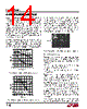
14 / 16 page  14 LT1761 Series dielectrics used are Z5U, Y5V, X5R and X7R. The Z5U and Y5V dielectrics are good for providing high capacitances in a small package, but exhibit strong voltage and tem- perature coefficients as shown in Figures 3 and 4. When used with a 5V regulator, a 10 µF Y5V capacitor can exhibit an effective value as low as 1 µF to 2µF over the operating temperature range. The X5R and X7R dielectrics result in more stable characteristics and are more suitable for use as the output capacitor. The X7R type has better stability across temperature, while the X5R is less expensive and is available in higher values. Voltage and temperature coefficients are not the only sources of problems. Some ceramic capacitors have a piezoelectric response. A piezoelectric device generates voltage across its terminals due to mechanical stress, similar to the way a piezoelectric accelerometer or Figure 4. Ceramic Capacitor Temperature Characteristics Figure 3. Ceramic Capacitor DC Bias Characteristics TEMPERATURE ( °C) –50 40 20 0 –20 –40 –60 –80 –100 25 75 1761 F04 –25 0 50 100 125 Y5V X5R BOTH CAPACITORS ARE 16V, 1210 CASE SIZE, 10 µF DC BIAS VOLTAGE (V) 1761 F03 20 0 –20 –40 –60 –80 –100 0 4 8 10 26 12 14 X5R Y5V 16 BOTH CAPACITORS ARE 16V, 1210 CASE SIZE, 10 µF APPLICATIO S I FOR ATIO microphone works. For a ceramic capacitor the stress can be induced by vibrations in the system or thermal transients. The resulting voltages produced can cause appreciable amounts of noise, especially when a ceramic capacitor is used for noise bypassing. A ceramic capaci- tor produced Figure 5’s trace in response to light tapping from a pencil. Similar vibration induced behavior can masquerade as increased output voltage noise. 100ms/DIV 1761 F05 VOUT 500 µV/DIV Figure 5. Noise Resulting from Tapping on a Ceramic Capacitor LT1761-5 COUT = 10µF CBYP = 0.01µF ILOAD = 100mA Thermal Considerations The power handling capability of the device will be limited by the maximum rated junction temperature (125 °C). The power dissipated by the device will be made up of two components: 1. Output current multiplied by the input/output voltage differential: (IOUT)(VIN – VOUT), and 2. GND pin current multiplied by the input voltage: (IGND)(VIN). The ground pin current can be found by examining the GND Pin Current curves in the Typical Performance Char- acteristics section. Power dissipation will be equal to the sum of the two components listed above. The LT1761 series regulators have internal thermal limit- ing designed to protect the device during overload condi- tions. For continuous normal conditions, the maximum junction temperature rating of 125 °C must not be exceeded. It is important to give careful consideration to all sources of thermal resistance from junction to ambient. Additional heat sources mounted nearby must also be considered. For surface mount devices, heat sinking is accomplished by using the heat spreading capabilities of the PC board |
|
|
Enlace URL |
| ¿ALLDATASHEET es útil para Ud.? [ DONATE ] |
Todo acerca de Alldatasheet | Publicidad | Contáctenos | Política de Privacidad | Enlace a la hoja de datos | Intercambio de Enlaces | Lista de Fabricantes All Rights Reserved©Alldatasheet.com |
| Russian : Alldatasheetru.com | Korean : Alldatasheet.co.kr | Spanish : Alldatasheet.es | French : Alldatasheet.fr | Italian : Alldatasheetit.com Portuguese : Alldatasheetpt.com | Polish : Alldatasheet.pl | Vietnamese : Alldatasheet.vn Indian : Alldatasheet.in | Mexican : Alldatasheet.com.mx | British : Alldatasheet.co.uk | New Zealand : Alldatasheet.co.nz |
|
Family Site : ic2ic.com |
icmetro.com |
 Mexican ▼
 English
 Chinese
 German
 Japanese
 Russian
 Korean
 Spanish
 French
 Italian
 Portuguese
 Polish
 Vietnamese
 Indian
 Mexican
 British
 New Zealand