 |
Motor de Búsqueda de Datasheet de Componentes Electrónicos |
|
|
Motor de Búsqueda de Datasheet de Componentes Electrónicos |
|
TA7368PL-R10-R Datasheet(PDF) 5 Page - Unisonic Technologies |
|
|
|||||||||||||||||||||||||||||
TA7368PL-R10-R Datasheet(HTML) 5 Page - Unisonic Technologies |
|
|
5 / 7 page 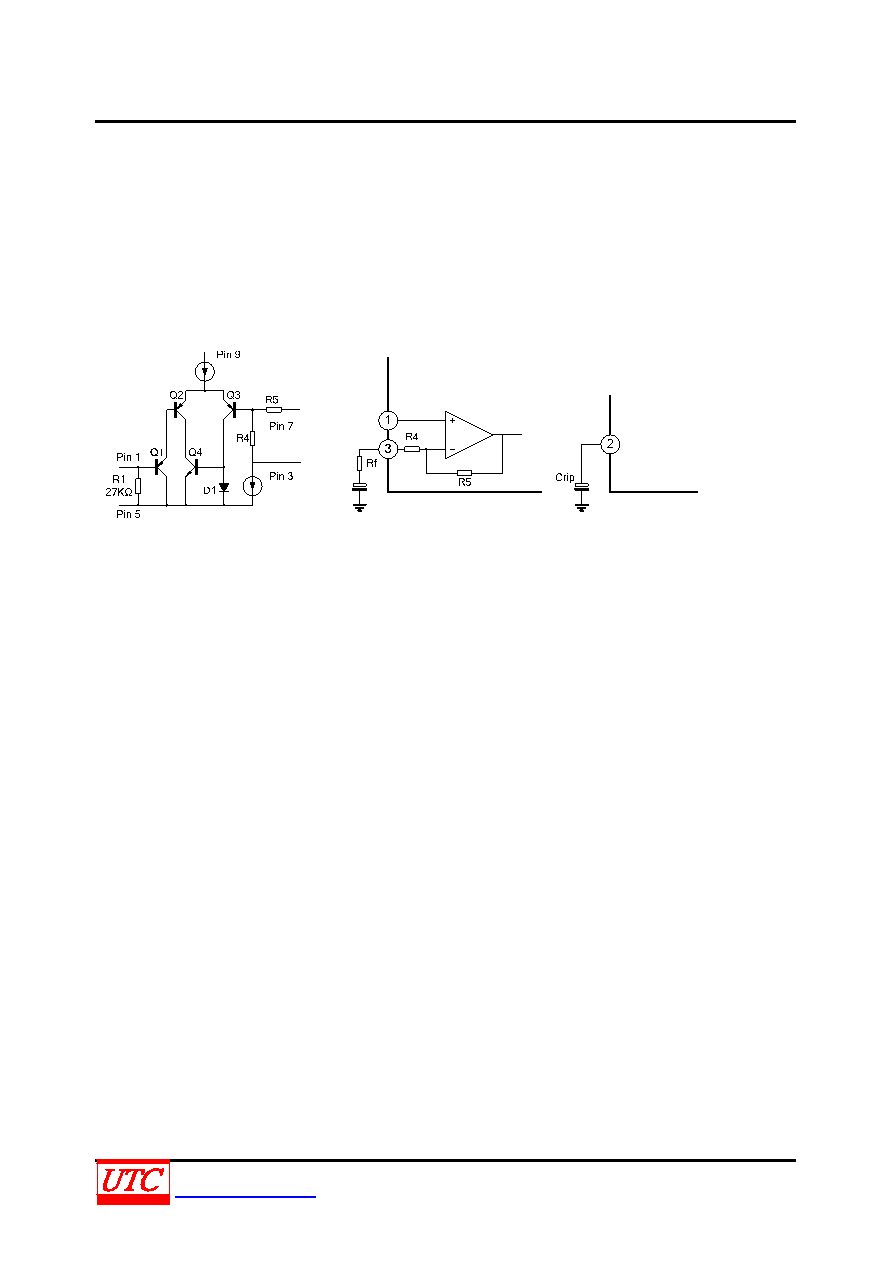 TA7368P LINEAR INTEGRATED CIRCUIT UNISONICTECHNOLOGIESCO.,LTD 5 of 7 www.unisonic.com.tw QW-R107-009.F PRECAUTION FOR APPLICATION 1. Input stage (Figure 1) The input stage of power amplifier is comprised of a PNP differential pair( Q2 and Q3) preceded by a PNP emitter follower(Q1) which allows DC referencing of the source signal to GND. This eliminates the need for an input coupling capacitor. However, in case the brush noise of volume becomes a problem, provide serially a coupling capacitor to the input side. 2. Adjustment of the voltage gain (Figure 2) The voltage gain is fixed at GV=40dB by the resistors( R4 and R5) in IC. Its reduction is possible through adding RF as shown in Figure 2. In this case, the voltage gain is obtained by the following equation: GV=20log(R5+R4+ RF)/(R4+ RF). It is recommended to use this IC with the voltage gain of GV=28dB or over. Figure 1 Figure 2 Figure 3 3. Ripple Rejection (Figure 3) Adding Crip, to the ripple terminal 2 as shown in Figure 3, the ripple rejection ratio is improved from -25dB to -45dB. 4. Power dissipation Casre should be taken to use IC below maximum power dissipation because it may be over maximum rating depending on operating condition. PD=900mW (TA=25C) 5. Phase-compensation Small temperature coefficient and excellent frequency characteristics is needed by capacitor below: *Oscillation preventing capacitor for power amplifier output *Bypass capacitor for ripple filter *Capacitor between VCC and GND |
|
|
Enlace URL |
| ¿ALLDATASHEET es útil para Ud.? [ DONATE ] |
Todo acerca de Alldatasheet | Publicidad | Contáctenos | Política de Privacidad | Enlace a la hoja de datos | Intercambio de Enlaces | Lista de Fabricantes All Rights Reserved©Alldatasheet.com |
| Russian : Alldatasheetru.com | Korean : Alldatasheet.co.kr | Spanish : Alldatasheet.es | French : Alldatasheet.fr | Italian : Alldatasheetit.com Portuguese : Alldatasheetpt.com | Polish : Alldatasheet.pl | Vietnamese : Alldatasheet.vn Indian : Alldatasheet.in | Mexican : Alldatasheet.com.mx | British : Alldatasheet.co.uk | New Zealand : Alldatasheet.co.nz |
|
Family Site : ic2ic.com |
icmetro.com |
 Mexican ▼
 English
 Chinese
 German
 Japanese
 Russian
 Korean
 Spanish
 French
 Italian
 Portuguese
 Polish
 Vietnamese
 Indian
 Mexican
 British
 New Zealand


