|
Motor de Búsqueda de Datasheet de Componentes Electrónicos |
|
|
Motor de Búsqueda de Datasheet de Componentes Electrónicos |
|
UPD720100AGM-8ED Datasheet(PDF) 17 Page - NEC |
|
|
|||||||||||||||||||||||||||||
UPD720100AGM-8ED Datasheet(HTML) 17 Page - NEC |
|
|
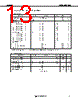
17 / 32 page 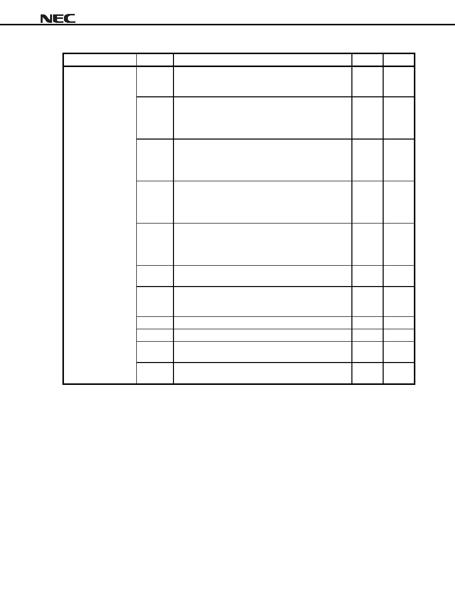 Data Sheet S15535EJ2V0DS 17 µµµµPD720100A Power Consumption Parameter Symbol Condition TYP. Unit PWD0-0 The power consumption under the state without suspend. Device state = D0, All the ports does not connect to any function. Note 1 168.0 mA The power consumption under the state without suspend. Device state = D0, The number of active ports is 2. Note 2 PWD0-2 EHCI host controller is inactive. EHCI host controller is active. 186.2 301.6 mA mA The power consumption under the state without suspend. Device state = D0, The number of active ports is 3. Note 2 PWD0-3 EHCI host controller is inactive. EHCI host controller is active. 195.3 368.4 mA mA The power consumption under the state without suspend. Device state = D0, The number of active ports is 4. Note 2 PWD0-4 EHCI host controller is inactive. EHCI host controller is active. 204.4 435.2 mA mA The power consumption under the state without suspend. Device state = D0, The number of active ports is 5. Note 2 PWD0-5 EHCI host controller is inactive. EHCI host controller is active. 213.5 502.0 mA mA PWD0_S The power consumption under suspend state. Device state = D0, The internal clock is stopped. Note 3 136.2 mA PWD0_C The power consumption under suspend state during PCI clock is stopped by CRUN0. Device state = D0, The internal clock is stopped. Note 3 113.0 mA PWD1 Device state = D1, Analog PLL output is stopped. Note 3, 4 24.7 mA PWD2 Device state = D2, Analog PLL output is stopped. Note 3, 4 10.9 mA PWD3H Device state = D3hot, PIN_EN = High Analog PLL output is stopped. Note 3, 4 10.9 mA Power Consumption PWD3C Device state = D3cold , PIN_EN = Low Oscillator output is stopped. Note 3, 4, 5 650 µA Notes 1. When any device is not connected to all the ports of HC, the power consumption for HC does not depend on the number of active ports. 2. The number of active ports is set by the value of Port No field in PCI configuration space EXT register. 3. For the condition of clock stop, see µµµµPD720100A User’s Manual 7.3 Control for System Clock Operation. 4. When the device state = D1, PCI clock is defined as it is running. When the device state = D2 or D3, PCI clock is defined as it is stopped. 5. If 48 MHz oscillator clock-in is used, power consumption for oscillator block + HC chip will be more than 15 mA. |
|
Enlace URL |
| ¿ALLDATASHEET es útil para Ud.? [ DONATE ] |
Todo acerca de Alldatasheet | Publicidad | Contáctenos | Política de Privacidad | Enlace a la hoja de datos | Intercambio de Enlaces | Lista de Fabricantes All Rights Reserved©Alldatasheet.com |
| Russian : Alldatasheetru.com | Korean : Alldatasheet.co.kr | Spanish : Alldatasheet.es | French : Alldatasheet.fr | Italian : Alldatasheetit.com Portuguese : Alldatasheetpt.com | Polish : Alldatasheet.pl | Vietnamese : Alldatasheet.vn Indian : Alldatasheet.in | Mexican : Alldatasheet.com.mx | British : Alldatasheet.co.uk | New Zealand : Alldatasheet.co.nz |
|
Family Site : ic2ic.com |
icmetro.com |
 Mexican ▼
 English
 Chinese
 German
 Japanese
 Russian
 Korean
 Spanish
 French
 Italian
 Portuguese
 Polish
 Vietnamese
 Indian
 Mexican
 British
 New Zealand