 |
Motor de Búsqueda de Datasheet de Componentes Electrónicos |
|
|
Motor de Búsqueda de Datasheet de Componentes Electrónicos |
|
OP27AFKB Datasheet(PDF) 16 Page - Texas Instruments |
|
|
|
|||||||||||||||||||||||||||||
OP27AFKB Datasheet(HTML) 16 Page - Texas Instruments |
|
|
16 / 23 page 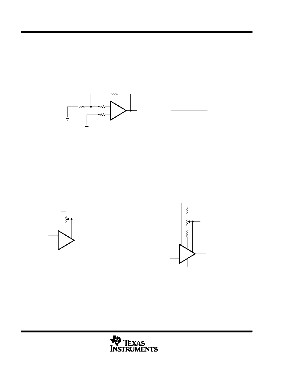 OP27A, OP27C LOW-NOISE HIGH-SPEED PRECISION OPERATIONAL-AMPLIFIER SLOS100E − FEBRUARY 1989 − REVISED FEBRUARY 2010 16 POST OFFICE BOX 655303 • DALLAS, TEXAS 75265 APPLICATION INFORMATION noise testing (continued) When measuring noise on a large number of units, a noise-voltage density test is recommended. A 10-Hz noise-voltage density measurement correlates well with a 0.1-Hz to 10-Hz peak-to-peak noise reading since both results are determined by the white noise and the location of the 1/f corner frequency. Figure 27 shows a circuit measuring current noise and the formula for calculating current noise. + − 10k Ω Vno 100 Ω 500 k Ω 500 k Ω [Vno2 − (130 nV)2]1/2 1 M Ω × 100 In = Figure 27. Current Noise Test Circuit and Formula offset voltage adjustment The input offset voltage and temperature coefficient of the OP27 are permanently trimmed to a low level at wafer testing. However, if further adjustment of VIO is necessary, using a 10-kΩ nulling potentiometer as shown in Figure 28 does not degrade the temperature coefficient αVIO. Trimming to a value other than zero creates an αVIO of VIO/300 μV/°C. For example, if VIO is adjusted to 300 μV, the change in αVIO is 1 μV/°C. The adjustment range with a 10-k Ω potentiometer is approximately ±2.5 mV. If a smaller adjustment range is needed, the sensitivity and resolution of the nulling can be improved by using a smaller potentiometer in conjunction with fixed resistors. The example in Figure 29 has an approximate null range of ±200 μV. + − −15 V Output 2 3 7 8 4 1 Input 6 15 V 10 k Ω −15 V Output 2 3 7 8 4 1 Input 6 4.7 k Ω Figure 28. Standard Input Offset Voltage Adjustment Figure 29. Input Offset Voltage Adjustment With Improved Sensitivity 15 V 1 k Ω 4.7 k Ω offset voltage and drift Unless proper care is exercised, thermoelectric effects caused by temperature gradients across dissimilar metals at the contacts to the input terminals can exceed the inherent temperature coefficient ∝VIO of the amplifier. Air currents should be minimized, package leads should be short, and the two input leads should be close together and at the same temperature. |
|
|
Enlace URL |
| ¿ALLDATASHEET es útil para Ud.? [ DONATE ] |
Todo acerca de Alldatasheet | Publicidad | Contáctenos | Política de Privacidad | Enlace a la hoja de datos | Intercambio de Enlaces | Lista de Fabricantes All Rights Reserved©Alldatasheet.com |
| Russian : Alldatasheetru.com | Korean : Alldatasheet.co.kr | Spanish : Alldatasheet.es | French : Alldatasheet.fr | Italian : Alldatasheetit.com Portuguese : Alldatasheetpt.com | Polish : Alldatasheet.pl | Vietnamese : Alldatasheet.vn Indian : Alldatasheet.in | Mexican : Alldatasheet.com.mx | British : Alldatasheet.co.uk | New Zealand : Alldatasheet.co.nz |
|
Family Site : ic2ic.com |
icmetro.com |
 Mexican ▼
 English
 Chinese
 German
 Japanese
 Russian
 Korean
 Spanish
 French
 Italian
 Portuguese
 Polish
 Vietnamese
 Indian
 Mexican
 British
 New Zealand


