|
Motor de Búsqueda de Datasheet de Componentes Electrónicos |
|
|
Motor de Búsqueda de Datasheet de Componentes Electrónicos |
|
EC3276NNMHR Datasheet(PDF) 10 Page - E-CMOS Corporation |
|
|
|||||||||||||||||||||||||||||
EC3276NNMHR Datasheet(HTML) 10 Page - E-CMOS Corporation |
|
|
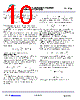
10 / 12 page  E-CMOS Corp. (www.ecmos.com.tw) Page 10 of 12 3G16N-Rev.P001 2.2A/32V Synchronous Rectified Step-Down Converter EC3276 Since the input capacitor (C1) absorbs the input switching current it requires an adequate ripple current rating. The RMS current in the input capacitor can be estimated by: The worst-case condition occurs at VIN = 2VOUT,where IC1 = ILOAD/2. For simplification, choose the input capacitor whose RMS current rating greater than half of the maximum load current. The input capacitor can be electrolytic, tantalum or ceramic. When using electrolytic or tantalum capacitors, a small, high quality ceramic capacitor, i.e. 0.1μF, should be placed as close to the IC as possible. When using ceramic capacitors, make sure that they have enough capacitance to provide sufficient charge to prevent excessive voltage ripple at input. The input voltage ripple for low ESR capacitors can be estimated by: Where C1 is the input capacitance value. Output Capacitor The output capacitor is required to maintain the DC output voltage. Ceramic, tantalum, or low ESR electrolytic capacitors are recommended. Low ESR capacitors are preferred to keep the output voltage ripple low. The output voltage ripple can be estimated by: Where C2 is the output capacitance value and RESR is the equivalent series resistance (ESR) value of the output capacitor. In the case of ceramic capacitors, the impedance at the switching frequency is dominated by the capacitance. The output voltage ripple is mainly caused by the capacitance. For simplification, the output voltage ripple can be estimated by: In the case of tantalum or electrolytic capacitors, the ESR dominates the impedance at the switching frequency. For simplification, the output ripple can be approximated to: The characteristics of the output capacitor also affect the stability of the regulation system. The EC3276 can be optimized for a wide range of capacitance and ESR values. Compensation Components EC3276 employs current mode control for easy compensation and fast transient response. The system stability and transient response are controlled through the COMP pin. COMP pin is the output of the internal trans-conductance error amplifier. A series capacitor-resistor combination sets a pole-zero combination to control the characteristics of the control system. The DC gain of the voltage feedback loop is given by: Where AVEA is the error amplifier voltage gain; GCS is the current sense transconductance and RLOAD is the load resistor value. The system has two poles of importance. One is due to the compensation capacitor (C3) and the output resistor of the error amplifier, and the other is due to the output capacitor and the load resistor. These poles are located at: Where GEA is the error amplifier transconductance. |
|
|
Enlace URL |
| ¿ALLDATASHEET es útil para Ud.? [ DONATE ] |
Todo acerca de Alldatasheet | Publicidad | Contáctenos | Política de Privacidad | Enlace a la hoja de datos | Intercambio de Enlaces | Lista de Fabricantes All Rights Reserved©Alldatasheet.com |
| Russian : Alldatasheetru.com | Korean : Alldatasheet.co.kr | Spanish : Alldatasheet.es | French : Alldatasheet.fr | Italian : Alldatasheetit.com Portuguese : Alldatasheetpt.com | Polish : Alldatasheet.pl | Vietnamese : Alldatasheet.vn Indian : Alldatasheet.in | Mexican : Alldatasheet.com.mx | British : Alldatasheet.co.uk | New Zealand : Alldatasheet.co.nz |
|
Family Site : ic2ic.com |
icmetro.com |
 Mexican ▼
 English
 Chinese
 German
 Japanese
 Russian
 Korean
 Spanish
 French
 Italian
 Portuguese
 Polish
 Vietnamese
 Indian
 Mexican
 British
 New Zealand