 |
Motor de Búsqueda de Datasheet de Componentes Electrónicos |
|
|
Motor de Búsqueda de Datasheet de Componentes Electrónicos |
|
The question interval is too short.
Please try again in a few seconds.

Hello, Please ask a question about MPM3810A Datasheet
# Example questions:
➢ How do the waveforms differ when the output current is 0.1a versus 2a at a 2v output?
➢ What is the typical supply current (quiescent current) of the mpm3810a at +25°c, based on the graphs provided?
➢ How does ambient temperature affect the p-fet current limit?
| Part No. | MPM3810A |
| Manufacturer | MPS |
| Size | 660 Kbytes |
| Pages | 19 pages |
| Description | 6V Input, 1.2A Module Synchronous Step-Down Converter with Integrated Inductor AEC-Q100 Qualified |

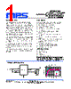

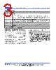
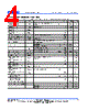






1. General Information & Overview
️· Device: MPM3810A - A Peak Simple Module with Integrated Inductor.
️· Function: This is a power module (likely a buck regulator or similar) designed for efficient voltage conversion. The "Peak Simple" designation suggests a simplified design for ease of use. The integrated inductor reduces external component count.
️· Datasheet Section: This excerpt focuses on "Typical Performance Characteristics." These plots show how the regulator behaves under various operating conditions.
2. Key Electrical Characteristics (from Data Tables)
️· Supply Voltage: Not directly stated but seems to operate efficiently around 5V (based on the plot titles).
️· Output Voltage: Can be configured for 1.2V and 1.8V output.
️· Output Current: Appears capable of delivering up to 1.2A continuously, although this depends on thermal management and operating conditions.
️· Operating Temperature: -40°C to +140°C (as indicated on several plots)
3. Summary of Plots & Observations (organized by plot title. It's hard to be exact without the visual graphs)
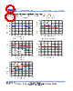
️· P-FET Current Limit vs. TA: The current limit of the P-FET changes with ambient temperature.
️· Switch Frequency vs. TA: The switching frequency also changes with temperature.
️· Enable On/Off vs. TA: Shows how the enable/disable function behaves with changing temperature.
️· Feedback Voltage vs. TA: The feedback voltage drifts with temperature.
️· Supply Current vs. TA: Supply current increases with temperature.
️· Steady State V IN / V OUT / I OUT: A series of plots demonstrating the behavior of the module at various output currents and voltage levels (1.2V and 1.8V outputs) under steady-state conditions. These include waveforms of the input voltage, output voltage, and output current. The steady state plots provide insight into efficiency and ripple behavior.
- Plots exist for:
■ Vout=1.2V, Iout=0.1A
■ Vout=1.2V, Iout=0.6A
■ Vout=1.2V, Iout=1.2A
■ Vout=1.8V, Iout=0.1A
■ Vout=1.8V, Iout=0.6A
■ Vout=1.8V, Iout=1.2A
4. Important Considerations (Based on Datasheet Excerpts)
️· Temperature Effects: Performance is affected by temperature. The feedback voltage, switching frequency, and current limit all vary. Thermal management is crucial.
️· Efficiency: Efficiency is not directly stated, but the steady-state plots (waveform analysis) could be used to approximate efficiency under different load conditions. It would be beneficial to examine the steady-state efficiency plots to determine the efficiency range.
️· Layout: Proper PCB layout is important for minimizing noise and ensuring stable operation.
️· Component Selection: While the inductor is integrated, other external components (input/output capacitors) will still be required. Proper selection of these capacitors is critical for performance.
Limitations & Next Steps
️· Image Dependence: A true understanding of this datasheet requires the actual visual graphs. I have done my best to summarize based on the plot titles.
️· Complete Datasheet: This is just an excerpt. The full datasheet will contain more detailed specifications, application circuits, and layout guidelines.
️· Application Notes: MPS (Monolithic Power Systems) likely has application notes for this device that provide practical design guidance.
1. General Information & Overview
️· Device: MPM3810A - A Peak Simple Module with Integrated Inductor.
️· Function: This is a power module (likely a buck regulator or similar) designed for efficient voltage conversion. The "Peak Simple" designation suggests a simplified design for ease of use. The integrated inductor reduces external component count.
️· Datasheet Section: This excerpt focuses on "Typical Performance Characteristics." These plots show how the regulator behaves under various operating conditions.
2. Key Electrical Characteristics (from Data Tables)
️· Supply Voltage: Not directly stated but seems to operate efficiently around 5V (based on the plot titles).
️· Output Voltage: Can be configured for 1.2V and 1.8V output.
️· Output Current: Appears capable of delivering up to 1.2A continuously, although this depends on thermal management and operating conditions.
️· Operating Temperature: -40°C to +140°C (as indicated on several plots)
3. Summary of Plots & Observations (organized by plot title. It's hard to be exact without the visual graphs)
️· P-FET Current Limit vs. TA: The current limit of the P-FET changes with ambient temperature.
️· Switch Frequency vs. TA: The switching frequency also changes with temperature.
️· Enable On/Off vs. TA: Shows how the enable/disable function behaves with changing temperature.
️· Feedback Voltage vs. TA: The feedback voltage drifts with temperature.
️· Supply Current vs. TA: Supply current increases with temperature.
️· Steady State V IN / V OUT / I OUT: A series of plots demonstrating the behavior of the module at various output currents and voltage levels (1.2V and 1.8V outputs) under steady-state conditions. These include waveforms of the input voltage, output voltage, and output current. The steady state plots provide insight into efficiency and ripple behavior.
- Plots exist for:
■ Vout=1.2V, Iout=0.1A
■ Vout=1.2V, Iout=0.6A
■ Vout=1.2V, Iout=1.2A
■ Vout=1.8V, Iout=0.1A
■ Vout=1.8V, Iout=0.6A
■ Vout=1.8V, Iout=1.2A
4. Important Considerations (Based on Datasheet Excerpts)
️· Temperature Effects: Performance is affected by temperature. The feedback voltage, switching frequency, and current limit all vary. Thermal management is crucial.
️· Efficiency: Efficiency is not directly stated, but the steady-state plots (waveform analysis) could be used to approximate efficiency under different load conditions. It would be beneficial to examine the steady-state efficiency plots to determine the efficiency range.
️· Layout: Proper PCB layout is important for minimizing noise and ensuring stable operation.
️· Component Selection: While the inductor is integrated, other external components (input/output capacitors) will still be required. Proper selection of these capacitors is critical for performance.
Limitations & Next Steps
️· Image Dependence: A true understanding of this datasheet requires the actual visual graphs. I have done my best to summarize based on the plot titles.
️· Complete Datasheet: This is just an excerpt. The full datasheet will contain more detailed specifications, application circuits, and layout guidelines.
️· Application Notes: MPS (Monolithic Power Systems) likely has application notes for this device that provide practical design guidance.
| Part No. | MPM3810A |
| Manufacturer | MPS |
| Size | 660 Kbytes |
| Pages | 19 pages |
| Description | 6V Input, 1.2A Module Synchronous Step-Down Converter with Integrated Inductor AEC-Q100 Qualified |
| ¿ALLDATASHEET es útil para Ud.? [ DONATE ] |
Todo acerca de Alldatasheet | Publicidad | Contáctenos | Política de Privacidad | Enlace a la hoja de datos | Intercambio de Enlaces | Lista de Fabricantes All Rights Reserved©Alldatasheet.com |
| Russian : Alldatasheetru.com | Korean : Alldatasheet.co.kr | Spanish : Alldatasheet.es | French : Alldatasheet.fr | Italian : Alldatasheetit.com Portuguese : Alldatasheetpt.com | Polish : Alldatasheet.pl | Vietnamese : Alldatasheet.vn Indian : Alldatasheet.in | Mexican : Alldatasheet.com.mx | British : Alldatasheet.co.uk | New Zealand : Alldatasheet.co.nz |
|
Family Site : ic2ic.com |
icmetro.com |
 Mexican ▼
  English
 Chinese
 German
 Japanese
 Russian
 Korean
 Spanish
 French
 Italian
 Portuguese
 Polish
 Vietnamese
 Indian
 British
 New Zealand