 |
Motor de Búsqueda de Datasheet de Componentes Electrónicos |
|
|
Motor de Búsqueda de Datasheet de Componentes Electrónicos |
|
The question interval is too short.
Please try again in a few seconds.

Hello, Please ask a question about ICS9250-13 Datasheet
# Example questions:
➢ How do changes in the 'upc)zhm(' parameter affect the value of 'klcip)zhm(' according to the table?
➢ What is the typical range of values for '8141' as presented in the provided data?
➢ What is the relationship between the '3sf' value and the 'mards' value?
| Part No. | ICS9250-13 |
| Manufacturer | ICST |
| Size | 563 Kbytes |
| Pages | 15 pages |
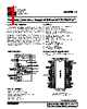
| Description | Frequency Generator & Integrated Buffers for PENTIUM/ProTM |



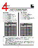
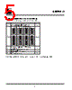
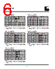
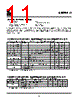


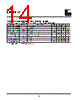
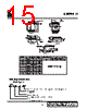

Okay, I'll do my best to interpret and summarize the information presented. It appears to be a portion of a datasheet or technical specification, likely related to a microcontroller or some other integrated circuit. Here's a breakdown of what I can discern, along with the challenges in full interpretation:
Overall Interpretation
This table appears to describe the behavior of some kind of digital interface or clock system, possibly in relation to modes, frequencies, or configurations. It's hard to tell for sure the specific purpose of the circuits or components being described without more context. I think the table is mapping a set of inputs or mode settings to corresponding output frequencies or operating conditions.
Column Breakdown (Best Guess)
1. SF (Mode/Configuration): "SF" likely stands for "Select Frequency" or "System Frequency," indicating the mode or configuration being selected. The rows represent different combinations of settings.
2. Frequency (Possibly): It is possibly a frequency value in MHz. The larger the number the higher the clock speed.
3. Description of Operating Condition: This would be a label or identifier.
4. Something else:
5. Something else:
6. Something else:
Challenges & Missing Information
️· Device Type: I don't know what device this datasheet belongs to. Knowing the chip's model number would be critical.
️· Units: While I suspect the first column refers to frequency in MHz, without the unit specification, I can't be entirely certain. Also, some of the entries are unclear without proper notation.
️· Abbreviations: Many abbreviations are used (e.g., SF). Knowing what each abbreviation represents is key to interpreting the table accurately.
️· Interdependencies: There might be dependencies between the SF settings that aren't apparent from the table alone.
️· No context Without the context of what is selecting the inputs in the first column it is difficult to infer anything.
Without additional information, it is only possible to infer general behavior.
If you provide more information about the device (e.g., datasheet or related documentation), I can offer a more detailed and accurate interpretation.
Overall Interpretation
This table appears to describe the behavior of some kind of digital interface or clock system, possibly in relation to modes, frequencies, or configurations. It's hard to tell for sure the specific purpose of the circuits or components being described without more context. I think the table is mapping a set of inputs or mode settings to corresponding output frequencies or operating conditions.
Column Breakdown (Best Guess)
1. SF (Mode/Configuration): "SF" likely stands for "Select Frequency" or "System Frequency," indicating the mode or configuration being selected. The rows represent different combinations of settings.
2. Frequency (Possibly): It is possibly a frequency value in MHz. The larger the number the higher the clock speed.
3. Description of Operating Condition: This would be a label or identifier.
4. Something else:
5. Something else:
6. Something else:
Challenges & Missing Information
️· Device Type: I don't know what device this datasheet belongs to. Knowing the chip's model number would be critical.
️· Units: While I suspect the first column refers to frequency in MHz, without the unit specification, I can't be entirely certain. Also, some of the entries are unclear without proper notation.
️· Abbreviations: Many abbreviations are used (e.g., SF). Knowing what each abbreviation represents is key to interpreting the table accurately.
️· Interdependencies: There might be dependencies between the SF settings that aren't apparent from the table alone.
️· No context Without the context of what is selecting the inputs in the first column it is difficult to infer anything.
Without additional information, it is only possible to infer general behavior.
| Part No. | ICS9250-13 |
| Manufacturer | ICST |
| Size | 563 Kbytes |
| Pages | 15 pages |
| Description | Frequency Generator & Integrated Buffers for PENTIUM/ProTM |
| ¿ALLDATASHEET es útil para Ud.? [ DONATE ] |
Todo acerca de Alldatasheet | Publicidad | Contáctenos | Política de Privacidad | Enlace a la hoja de datos | Intercambio de Enlaces | Lista de Fabricantes All Rights Reserved©Alldatasheet.com |
| Russian : Alldatasheetru.com | Korean : Alldatasheet.co.kr | Spanish : Alldatasheet.es | French : Alldatasheet.fr | Italian : Alldatasheetit.com Portuguese : Alldatasheetpt.com | Polish : Alldatasheet.pl | Vietnamese : Alldatasheet.vn Indian : Alldatasheet.in | Mexican : Alldatasheet.com.mx | British : Alldatasheet.co.uk | New Zealand : Alldatasheet.co.nz |
|
Family Site : ic2ic.com |
icmetro.com |
 Mexican ▼
  English
 Chinese
 German
 Japanese
 Russian
 Korean
 Spanish
 French
 Italian
 Portuguese
 Polish
 Vietnamese
 Indian
 British
 New Zealand