 |
Motor de Búsqueda de Datasheet de Componentes Electrónicos |
|
|
Motor de Búsqueda de Datasheet de Componentes Electrónicos |
|
The question interval is too short.
Please try again in a few seconds.

Hello, Please ask a question about LTC485CS8 Datasheet
# Example questions:
➢ What is the maximum specified supply current across the operating temperature range, as indicated in the graphs?
➢ What is the range of receiver input threshold voltage across a temperature range of -25°c to 75°c?
➢ What is the typical differential output voltage of the driver at an output current of 1ma, according to the provided typical characteristics graphs?
| Part No. | LTC485CS8 |
| Manufacturer | LINER |
| Size | 327 Kbytes |
| Pages | 12 pages |
| Description | Low Power RS485 Interface Transceiver |


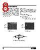


1. General Overview & Functionality
️· This document pertains to the LTC485, likely a transceiver or driver for RS-485 communication.
️· It's designed for bidirectional data transmission.
️· Key features appear to include: driver skew adjustment, TTL compatible inputs, and operation over a range of temperatures.
2. Electrical Characteristics (Key Values)
This is a condensed list, as the datasheet is filled with values. *See individual graph explanations for detailed information*
️· Supply Voltage: Not explicitly stated, but operation likely around 5V (based on TTL compatibility).
️· Data Rate: Not directly specified, but suitable for RS-485 communication.
️· Driver Output Voltage: Dependent on output current and temperature (see graphs).
️· Receiver Input Thresholds: TTL compatible.
️· Power Consumption: See graphs below for supply current vs. temperature.
3. Timing Characteristics (Important for RS-485 implementation)
️· Driver Skew: There's a characteristic regarding driver skew, with a value that varies with temperature. (See TPC12 Graph)
️· Propagation Delays: There's mention of `tPLH` and `tPHL` - which are key propagation delay characteristics.
4. Graphs and their Interpretations (These are the most detailed part of the information)
️· TPC01: Driver Output Low/High Voltage vs Output Current: Shows how the driver output voltage changes depending on the output current selected, and the graph shows the voltage level at 25°C.
️· TPC02: Receiver Output Low/High Voltage vs Temperature: Illustrates how the receiver output voltage changes depending on the operating temperature.
️· TPC03: TTL Input Threshold vs Temperature: Displays the input threshold voltage for TTL compatibility changes over temperature.
️· TPC05: Driver Output Low Voltage vs. Temperature: Shows the relationship between output low voltage and temperature.
️· TPC06: Driver Output High Voltage vs. Temperature: Similar to above but for output high voltage.
️· TPC07: Supply Current vs. Temperature: Shows the power consumption of the chip at different temperatures.
️· TPC08: Receiver `|tPLH – tPHL|` vs. Temperature: Represents the skew between the propagation delays for the receiver.
️· TPC09: Driver Skew vs Temperature: Shows how the skew between drivers changes as the temperature changes.
️· TPC10: Driver Skew: Driver Enable/Disable: Shows how the driver skew changes with driver enable and disable states.
️· TPC11: Timing Characteristics: This graph is not visible.
️· TPC12: Timing Characteristics: This graph is not visible.
5. Functional Block Diagram
*The document doesn's contains a functional block diagram.*
Important Notes & Limitations:
️· Image Quality: The image quality is low, making precise readings from the graphs difficult. Some values may be inaccurate due to this.
️· Missing Information: The datasheet is incomplete. Key information like the full electrical specifications, pinout, and a functional block diagram are missing. The timing characteristics are completely unreadable in the provided screenshots.
️· Context: Without the full datasheet, understanding the precise application and limitations of the LTC485 is challenging.
️· Unreadable graphs Graphs TPC11 and TPC12 are not visible due to readability.
1. General Overview & Functionality
️· This document pertains to the LTC485, likely a transceiver or driver for RS-485 communication.
️· It's designed for bidirectional data transmission.
️· Key features appear to include: driver skew adjustment, TTL compatible inputs, and operation over a range of temperatures.
2. Electrical Characteristics (Key Values)
This is a condensed list, as the datasheet is filled with values. *See individual graph explanations for detailed information*
️· Supply Voltage: Not explicitly stated, but operation likely around 5V (based on TTL compatibility).
️· Data Rate: Not directly specified, but suitable for RS-485 communication.
️· Driver Output Voltage: Dependent on output current and temperature (see graphs).
️· Receiver Input Thresholds: TTL compatible.
️· Power Consumption: See graphs below for supply current vs. temperature.
3. Timing Characteristics (Important for RS-485 implementation)
️· Driver Skew: There's a characteristic regarding driver skew, with a value that varies with temperature. (See TPC12 Graph)
️· Propagation Delays: There's mention of `tPLH` and `tPHL` - which are key propagation delay characteristics.
4. Graphs and their Interpretations (These are the most detailed part of the information)
️· TPC01: Driver Output Low/High Voltage vs Output Current: Shows how the driver output voltage changes depending on the output current selected, and the graph shows the voltage level at 25°C.
️· TPC02: Receiver Output Low/High Voltage vs Temperature: Illustrates how the receiver output voltage changes depending on the operating temperature.
️· TPC03: TTL Input Threshold vs Temperature: Displays the input threshold voltage for TTL compatibility changes over temperature.
️· TPC05: Driver Output Low Voltage vs. Temperature: Shows the relationship between output low voltage and temperature.
️· TPC06: Driver Output High Voltage vs. Temperature: Similar to above but for output high voltage.
️· TPC07: Supply Current vs. Temperature: Shows the power consumption of the chip at different temperatures.
️· TPC08: Receiver `|tPLH – tPHL|` vs. Temperature: Represents the skew between the propagation delays for the receiver.
️· TPC09: Driver Skew vs Temperature: Shows how the skew between drivers changes as the temperature changes.
️· TPC10: Driver Skew: Driver Enable/Disable: Shows how the driver skew changes with driver enable and disable states.
️· TPC11: Timing Characteristics: This graph is not visible.
️· TPC12: Timing Characteristics: This graph is not visible.
5. Functional Block Diagram
*The document doesn's contains a functional block diagram.*
Important Notes & Limitations:
️· Image Quality: The image quality is low, making precise readings from the graphs difficult. Some values may be inaccurate due to this.
️· Missing Information: The datasheet is incomplete. Key information like the full electrical specifications, pinout, and a functional block diagram are missing. The timing characteristics are completely unreadable in the provided screenshots.
️· Context: Without the full datasheet, understanding the precise application and limitations of the LTC485 is challenging.
️· Unreadable graphs Graphs TPC11 and TPC12 are not visible due to readability.
| Part No. | LTC485CS8 |
| Manufacturer | LINER |
| Size | 327 Kbytes |
| Pages | 12 pages |
| Description | Low Power RS485 Interface Transceiver |
| ¿ALLDATASHEET es útil para Ud.? [ DONATE ] |
Todo acerca de Alldatasheet | Publicidad | Contáctenos | Política de Privacidad | Enlace a la hoja de datos | Intercambio de Enlaces | Lista de Fabricantes All Rights Reserved©Alldatasheet.com |
| Russian : Alldatasheetru.com | Korean : Alldatasheet.co.kr | Spanish : Alldatasheet.es | French : Alldatasheet.fr | Italian : Alldatasheetit.com Portuguese : Alldatasheetpt.com | Polish : Alldatasheet.pl | Vietnamese : Alldatasheet.vn Indian : Alldatasheet.in | Mexican : Alldatasheet.com.mx | British : Alldatasheet.co.uk | New Zealand : Alldatasheet.co.nz |
|
Family Site : ic2ic.com |
icmetro.com |
 Mexican ▼
  English
 Chinese
 German
 Japanese
 Russian
 Korean
 Spanish
 French
 Italian
 Portuguese
 Polish
 Vietnamese
 Indian
 British
 New Zealand