|
Motor de Búsqueda de Datasheet de Componentes Electrónicos |
|
|
Motor de Búsqueda de Datasheet de Componentes Electrónicos |
|
LTC485CS8 Datasheet(PDF) 7 Page - Linear Technology |
|
|
|||||||||||||||||||||||||||||
LTC485CS8 Datasheet(HTML) 7 Page - Linear Technology |
|
|
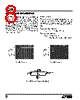
7 / 12 page  7 LTC485 APPLICATIO S I FOR ATIO Basic Theory of Operation Previous RS485 transceivers have been designed using bipolar technology because the common-mode range of the device must extend beyond the supplies and the device must be immune to ESD damage and latchup. Unfortu- nately, the bipolar devices draw a large amount of supply current, which is unacceptable for the numerous applica- tions that require low power consumption. The LTC485 is the first CMOS RS485/RS422 transceiver which features ultra-low power consumption without sacrificing ESD and latchup immunity. The LTC485 uses a proprietary driver output stage, which allows a common-mode range that extends beyond the power supplies while virtually eliminating latchup and providing excellent ESD protection. Figure 9 shows the LTC485 output stage while Figure 10 shows a conven- tional CMOS output stage. When the conventional CMOS output stage of Figure 10 enters a high impedance state, both the P-channel (P1) and the N-channel (N1) are turned off. If the output is then driven above VCC or below ground, the P + /N-well diode (D1) or the N + /P-substrate diode (D2) respectively will turn on and clamp the output to the supply. Thus, the output stage is no longer in a high impedance state and is not able to meet the RS485 common-mode range require- ment. In addition, the large amount of current flowing through either diode will induce the well known CMOS latchup condition, which could destroy the device. The LTC485 output stage of Figure 9 eliminates these problems by adding two Schottky diodes, SD3 and SD4. The Schottky diodes are fabricated by a proprietary modi- fication to the standard N-well CMOS process. When the output stage is operating normally, the Schottky diodes are forward biased and have a small voltage drop across them. When the output is in the high impedance state and is driven above VCC or below ground, the parasitic diodes D1 or D2 still turn on, but SD3 or SD4 will reverse bias and prevent current from flowing into the N-well or the sub- strate. Thus, the high impedance state is maintained even with the output voltage beyond the supplies. With no minority carrier current flowing into the N-well or sub- strate, latchup is virtually eliminated under power-up or power-down conditions. LOGIC VCC SD3 P1 D1 OUTPUT SD4 D2 N1 LTC485 • F09 LOGIC VCC P1 D1 OUTPUT D2 N1 LTC485 • F10 Figure 9. LTC485 Output Stage Figure 10. Conventional CMOS Output Stage |
|
|
Enlace URL |
| ¿ALLDATASHEET es útil para Ud.? [ DONATE ] |
Todo acerca de Alldatasheet | Publicidad | Contáctenos | Política de Privacidad | Enlace a la hoja de datos | Intercambio de Enlaces | Lista de Fabricantes All Rights Reserved©Alldatasheet.com |
| Russian : Alldatasheetru.com | Korean : Alldatasheet.co.kr | Spanish : Alldatasheet.es | French : Alldatasheet.fr | Italian : Alldatasheetit.com Portuguese : Alldatasheetpt.com | Polish : Alldatasheet.pl | Vietnamese : Alldatasheet.vn Indian : Alldatasheet.in | Mexican : Alldatasheet.com.mx | British : Alldatasheet.co.uk | New Zealand : Alldatasheet.co.nz |
|
Family Site : ic2ic.com |
icmetro.com |
 Mexican ▼
 English
 Chinese
 German
 Japanese
 Russian
 Korean
 Spanish
 French
 Italian
 Portuguese
 Polish
 Vietnamese
 Indian
 Mexican
 British
 New Zealand