 |
Motor de Búsqueda de Datasheet de Componentes Electrónicos |
|
|
Motor de Búsqueda de Datasheet de Componentes Electrónicos |
|
The question interval is too short.
Please try again in a few seconds.

Hello, Please ask a question about LM2716 Datasheet
# Example questions:
➢ Explain the significance of the right half plane zero (rhp zero) in a current mode controlled boost regulator and how it impacts the design process.
➢ The text details several components influencing stability. if a designer chooses a high esr output capacitor, what specific compensation technique is recommended to maintain stability, and why?
➢ What is the primary reason for calculating the minimum inductance value in a boost regulator design?
| Part No. | LM2716 |
| Manufacturer | NSC |
| Size | 563 Kbytes |
| Pages | 17 pages |
| Description | Dual (Step-up and Step-down) PWM DC/DC Converter |


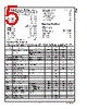
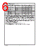
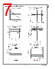


1. Boost Converter Overview & LM2716 Specifics
️· Boost Converter Function: Boost converters step up (increase) DC voltage.
️· LM2716 Role: A controller IC designed to manage the boost converter's operation.
️· Key Design Goals: Stability, transient response (how quickly it handles changes in load), efficiency.
2. Inductor and Diode Selection
️· Inductor Size Equation: `L = [1] / (2 * fsw * D * R_DSON)`
- `L`: Inductance (Henries)
- `fsw`: Switching Frequency
- `D`: Duty Cycle (Ratio of on-time to total time)
- `R_DSON`: On-resistance of the internal switch (from the datasheet graph)
️· Inductor Ripple Current: `Δi_L = (V_in / L) * D`
️· Right Half Plane (RHP) Zero Frequency: `f_RHP = (I_LOAD) / (2 * L * C_out)`
- `I_LOAD`: Maximum Load Current
- `C_out`: Output Capacitance
️· Diode Considerations: Must handle reverse voltage equal to or greater than the output voltage, average current exceeding the maximum load current, and peak current during short circuits. Schottky diodes are recommended for lower voltage drop and improved efficiency.
3. Output Capacitor Selection and Compensation
️· Output Capacitor Equation (Ripple Voltage): `ΔV_out = 2 * Δi_L * R_ESR`
️· Pole-Zero Pair (Introduced by Output Capacitor ESR):
- Pole Frequency: `f_P1 = 1 / (2 * Pi * R_ESR * C_out)`
- Zero Frequency: `f_Z1 = 1 / (2 * Pi * R_L * C_out)`
■ `R_L`: Minimum Load Resistance
️· Compensation Components (R_C2 & C_C2): Used to shape the control loop's response. Recommended ranges:
- `5kΩ ≤ R_C2 ≤ 20kΩ` (Up to 200kΩ if C_C4 is used.)
- `680pF ≤ C_C2 ≤ 4.7nF`
️· Dominant Pole Frequency: Aim for 10Hz to 500Hz. This is achieved by setting R_C2 and C_C2 correctly.
4. Key Design Steps & Equations
1. Calculate Inductor Size (L): Using the inductor size equation.
2. Check RHP Zero Frequency: Ensure the control loop bandwidth is less than this frequency.
3. Choose Output Capacitor (C_out): Based on ripple voltage requirements.
4. Determine R_C2 and C_C2: Start with values within the recommended ranges to create a dominant pole.
5. Verify Dominant Pole Frequency: Ensure it falls within the 10Hz to 500Hz range.
6. Refine Values: Optimize for transient response by adjusting R_C2 and C_C2 in a lab setting.
5. High Output Capacitor ESR Compensation
️· If you *must* use a higher ESR output capacitor, you need to compensate for the zero introduced by that ESR. This is done by adding a resistor and capacitor to the feedback loop. The specific values depend on the capacitor's ESR.
Important Notes & Cautions (READ THESE CAREFULLY!)
️· Datasheet is Essential: This summary *cannot* replace the original LM2716 datasheet. Always refer to the datasheet for detailed specifications, graphs, and application information.
️· R<sub>DSON</sub> Variation: R<sub>DSON</sub> varies with input voltage. Consult the datasheet graph and use a value appropriate for your operating conditions.
️· Real-World Testing: These equations provide starting points. Always verify your design with real-world testing, especially transient response. Load steps are critical for observing stability and performance. A scope is essential.
️· Right Half Plane Zero Concerns: Careful calculations of the RHP zero are critical to stable operation and it can become unstable if the control loop bandwidth is too close to the RHP zero frequency.
️· Component Tolerances: Consider component tolerances (e.g., resistor accuracy, capacitor ESR variations) in your calculations and design.
️· Layout: PCB layout is *critical* for power converters. Proper grounding, short trace lengths, and component placement are essential for stability and efficiency.
️· Simulation: It is a good idea to simulate your power converter design and verify stability before building the circuit.
1. Boost Converter Overview & LM2716 Specifics
️· Boost Converter Function: Boost converters step up (increase) DC voltage.
️· LM2716 Role: A controller IC designed to manage the boost converter's operation.
️· Key Design Goals: Stability, transient response (how quickly it handles changes in load), efficiency.
2. Inductor and Diode Selection
️· Inductor Size Equation: `L = [1] / (2 * fsw * D * R_DSON)`
- `L`: Inductance (Henries)
- `fsw`: Switching Frequency
- `D`: Duty Cycle (Ratio of on-time to total time)
- `R_DSON`: On-resistance of the internal switch (from the datasheet graph)
️· Inductor Ripple Current: `Δi_L = (V_in / L) * D`
️· Right Half Plane (RHP) Zero Frequency: `f_RHP = (I_LOAD) / (2 * L * C_out)`
- `I_LOAD`: Maximum Load Current
- `C_out`: Output Capacitance
️· Diode Considerations: Must handle reverse voltage equal to or greater than the output voltage, average current exceeding the maximum load current, and peak current during short circuits. Schottky diodes are recommended for lower voltage drop and improved efficiency.
3. Output Capacitor Selection and Compensation
️· Output Capacitor Equation (Ripple Voltage): `ΔV_out = 2 * Δi_L * R_ESR`
️· Pole-Zero Pair (Introduced by Output Capacitor ESR):
- Pole Frequency: `f_P1 = 1 / (2 * Pi * R_ESR * C_out)`
- Zero Frequency: `f_Z1 = 1 / (2 * Pi * R_L * C_out)`
■ `R_L`: Minimum Load Resistance
️· Compensation Components (R_C2 & C_C2): Used to shape the control loop's response. Recommended ranges:
- `5kΩ ≤ R_C2 ≤ 20kΩ` (Up to 200kΩ if C_C4 is used.)
- `680pF ≤ C_C2 ≤ 4.7nF`
️· Dominant Pole Frequency: Aim for 10Hz to 500Hz. This is achieved by setting R_C2 and C_C2 correctly.
4. Key Design Steps & Equations
1. Calculate Inductor Size (L): Using the inductor size equation.
2. Check RHP Zero Frequency: Ensure the control loop bandwidth is less than this frequency.
3. Choose Output Capacitor (C_out): Based on ripple voltage requirements.
4. Determine R_C2 and C_C2: Start with values within the recommended ranges to create a dominant pole.
5. Verify Dominant Pole Frequency: Ensure it falls within the 10Hz to 500Hz range.
6. Refine Values: Optimize for transient response by adjusting R_C2 and C_C2 in a lab setting.
5. High Output Capacitor ESR Compensation
️· If you *must* use a higher ESR output capacitor, you need to compensate for the zero introduced by that ESR. This is done by adding a resistor and capacitor to the feedback loop. The specific values depend on the capacitor's ESR.
Important Notes & Cautions (READ THESE CAREFULLY!)
️· Datasheet is Essential: This summary *cannot* replace the original LM2716 datasheet. Always refer to the datasheet for detailed specifications, graphs, and application information.
️· R<sub>DSON</sub> Variation: R<sub>DSON</sub> varies with input voltage. Consult the datasheet graph and use a value appropriate for your operating conditions.
️· Real-World Testing: These equations provide starting points. Always verify your design with real-world testing, especially transient response. Load steps are critical for observing stability and performance. A scope is essential.
️· Right Half Plane Zero Concerns: Careful calculations of the RHP zero are critical to stable operation and it can become unstable if the control loop bandwidth is too close to the RHP zero frequency.
️· Component Tolerances: Consider component tolerances (e.g., resistor accuracy, capacitor ESR variations) in your calculations and design.
️· Layout: PCB layout is *critical* for power converters. Proper grounding, short trace lengths, and component placement are essential for stability and efficiency.
️· Simulation: It is a good idea to simulate your power converter design and verify stability before building the circuit.
| Part No. | LM2716 |
| Manufacturer | NSC |
| Size | 563 Kbytes |
| Pages | 17 pages |
| Description | Dual (Step-up and Step-down) PWM DC/DC Converter |
| ¿ALLDATASHEET es útil para Ud.? [ DONATE ] |
Todo acerca de Alldatasheet | Publicidad | Contáctenos | Política de Privacidad | Enlace a la hoja de datos | Intercambio de Enlaces | Lista de Fabricantes All Rights Reserved©Alldatasheet.com |
| Russian : Alldatasheetru.com | Korean : Alldatasheet.co.kr | Spanish : Alldatasheet.es | French : Alldatasheet.fr | Italian : Alldatasheetit.com Portuguese : Alldatasheetpt.com | Polish : Alldatasheet.pl | Vietnamese : Alldatasheet.vn Indian : Alldatasheet.in | Mexican : Alldatasheet.com.mx | British : Alldatasheet.co.uk | New Zealand : Alldatasheet.co.nz |
|
Family Site : ic2ic.com |
icmetro.com |
 Mexican ▼
  English
 Chinese
 German
 Japanese
 Russian
 Korean
 Spanish
 French
 Italian
 Portuguese
 Polish
 Vietnamese
 Indian
 British
 New Zealand