|
Motor de Búsqueda de Datasheet de Componentes Electrónicos |
|
|
Motor de Búsqueda de Datasheet de Componentes Electrónicos |
|
LTM4650 Datasheet(PDF) 6 Page - Analog Devices |
|
|
|||||||||||||||||||||||||||||
LTM4650 Datasheet(HTML) 6 Page - Analog Devices |
|
|
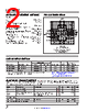
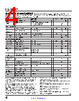
6 / 36 page  LTM4650-2 6 Rev. 0 For more information www.analog.com TYPICAL PERFORMANCE CHARACTERISTICS Single-Phase Short-Circuit Protection with 25A Single-Phase Short-Circuit Protection with No load Single-Phase Start-Up with 25A 20ms/DIV VSW 10V/DIV VOUT 0.5V/DIV IIN 1A/DIV 46502 G10 12VIN, 1.2VOUT, 500kHz COUT = 470µF ×1 POSCAP + 100µF ×2 CERAMIC, CSS = 0.1 F 50 s/DIV VSW 10V/DIV VOUT 0.5V/DIV IIN 1A/DIV 46502 G11 12VIN, 1.2VOUT, 500kHz COUT = 470µF ×1 POSCAP + 100µF ×2 CERAMIC, CSS = 0.1µF 50µs/DIV VSW 10V/DIV VOUT 0.5V/DIV IIN 2A/DIV 46502 G12 12VIN, 1.2VOUT, 500kHz COUT = 470µF ×1 POSCAP + 100µF ×2 CERAMIC PIN FUNCTIONS VOUT1 (A1–A5, B1–B5, C1–C4): Power Output Pins. Apply output load between these pins and GND pins. Recommend placing output decoupling capacitance directly between these pins and GND pins. See Table 4. GND (A6–A7, B6–B7, D1–D4, D9–D12, E1–E4, E10–E12, F1–F3, F10–F12, G1, G3, G10, G12, H1–H7, H9–H12, J1, J5, J8, J12, K1, K5–K8, K12, L1, L12, M1, M12): Power Ground Pins for Both Input and Output Returns. VOUT2 (A8–A12, B8–B12, C9–C12): Power Output Pins. Apply output load between these pins and GND pins. Recommend placing output decoupling capacitance directly between these pins and GND pins. See Table 4. VOUTS1, VOUTS2 (C5, C8): This pin is connected to the top of the internal top feedback resistor for each output. The pin can be directly connected to its specific output, or connected to DIFFOUT when the remote sense amplifier is used. In paralleling modules, one of the VOUTS pins is con- nected to the DIFFOUT pin in remote sensing or directly to VOUT with no remote sensing. It is very important to connect these pins to either the DIFFOUT or VOUT since this is the feedback path and cannot be left open. See the Applications Information section. fSET (C6): Frequency Set Pin. A 10µA current is sourced from this pin. A resistor from this pin to ground sets a volt- age that programs the operating frequency. Alternatively, this pin can be driven with a DC voltage that can set the operating frequency. See the Applications Information section. SGND (C7, D6, G6–G7, F6–F7): Signal Ground Pin. Return ground path for all analog and low-power circuitry. Tie a single connection to the output capacitor GND in the application. See the layout guidelines in Figure 23. VFB1, VFB2 (D5, D7): The Negative Input of the Error Amplifier for Each Channel. Internally, this pin is con- nected to VOUTS1 or VOUTS2 with a 60.4kΩ precision resistor. Different output voltages can be programmed with an additional resistor between VFB and GND pins. In PolyPhase® operation, tying the VFB pins together allows for parallel operation. See the Applications Information section for details. TRACK1, TRACK2 (E5, D8): Output Voltage Tracking Pin and Soft-Start Inputs. Each channel has a 1.3µA pull-up current source. When one channel is configured to be the main of the two channels, then a capacitor from this pin (Recommended to use test points to monitor signal pin connections.) PACKAGE ROW AND COLUMN LABELING MAY VARY AMONG µModule PRODUCTS. REVIEW EACH PACKAGE LAYOUT CAREFULLY. |
|
Enlace URL |
| ¿ALLDATASHEET es útil para Ud.? [ DONATE ] |
Todo acerca de Alldatasheet | Publicidad | Contáctenos | Política de Privacidad | Enlace a la hoja de datos | Intercambio de Enlaces | Lista de Fabricantes All Rights Reserved©Alldatasheet.com |
| Russian : Alldatasheetru.com | Korean : Alldatasheet.co.kr | Spanish : Alldatasheet.es | French : Alldatasheet.fr | Italian : Alldatasheetit.com Portuguese : Alldatasheetpt.com | Polish : Alldatasheet.pl | Vietnamese : Alldatasheet.vn Indian : Alldatasheet.in | Mexican : Alldatasheet.com.mx | British : Alldatasheet.co.uk | New Zealand : Alldatasheet.co.nz |
|
Family Site : ic2ic.com |
icmetro.com |
 Mexican ▼
 English
 Chinese
 German
 Japanese
 Russian
 Korean
 Spanish
 French
 Italian
 Portuguese
 Polish
 Vietnamese
 Indian
 Mexican
 British
 New Zealand