|
Motor de Búsqueda de Datasheet de Componentes Electrónicos |
|
|
Motor de Búsqueda de Datasheet de Componentes Electrónicos |
|
SP6128ACY/TR Datasheet(PDF) 8 Page - Sipex Corporation |
|
|
|||||||||||||||||||||||||||||
SP6128ACY/TR Datasheet(HTML) 8 Page - Sipex Corporation |
|
|
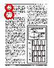
8 / 10 page  8 Rev. 08/19/05 SP6128A Low Voltage, Synchronous Step Down PWM Controller © Copyright 2005 Sipex Corporation - V(Diode) V ~ 0 V 5 V NON-OVERLAP GH(GL) 10 % 90 % FALL TIME 2 V GL(GH) 10 % 90 % RISE TIME 5 V 2 V GATE DRIVER TEST CONDITIONS TIME ~ 2*V(VIN) ~ V(VIN) BST Voltage SWN V(VCC=VIN) Voltage Voltage Voltage V(BST) GL GH V(VCC) 0 V 0 V switch. The ISET current has a temperature coef- ficient in an effort to first order match the thermal characteristics of the RDS(ON) of the high side NMOS switch. It assumed that the SP6128A will be used in compact designs where there is a high amount of thermal coupling between the high side switch and the controller. Discontinuous Start Up Today’s distributed power systems require mul- tiple supply voltages, such as core and I/O voltages. In many applications, there’s require- ment on the maximum voltage difference al- lowed between these supplies at any time. This requirement can be potentially violated during power start up when individual power supply ramps up in sequence or in different slew rates. As a solution, system designers often pre-charge power supplies through an external circuit prior to start up. Unfortunately, under this condition many existing synchronous controllers turn on the low side MOSFET during soft start for a long period of time, thereby, discharging the output capacitors. The discharge period creates a number of problems. One is the obvious prob- lem of losing the intended pre-charged output voltage. Another problem is a build up of exces- sive and unchecked current in the low side MOSFET and inductor. Lastly, this uncontrolled discharge current creates conditions that could damage either the distributed power supplies or the rather expensive “load” ICs. To prevent soft start from discharging the pre- charged output, SP6128A has built-in discon- tinuous start up. This operation disables the low side MOSFET driver GL during start up until either there is GH pulse or the internal SSTART reaches Vcc-1V. This feature eliminates the output discharging path during start up. During the steady state operation, the GL is fully en- gaged, and the operation is identical to regular synchronous buck converters. Output Drivers The SP6128A, unlike some other bipolar con- troller IC’s, incorporates gate drivers with rail- to-rail swing that help prevent spurious turn on due to capacitive coupling. The driver stage consists of one high side NMOS, 4 Ω driver, GH, and one low side, 4 Ω, NMOS driver, GL, optimized for driving external power MOSFET’s in a synchronous buck topology. The output drivers also provide gate drive non-overlap mechanism that provides a dead time between GH and GL transitions to avoid potential shoot- through problems in the external MOSFETs. The following figure shows typical waveforms for the output drivers. As with all synchronous designs, care must be taken to ensure that the MOSFETs are properly chosen for non-overlap time, enhancement gate drive voltage, “on” resistance RDS(ON), reverse transfer capacitance Crss, input voltage and maximum output current. OPERATION: continued |
|
|
Enlace URL |
| ¿ALLDATASHEET es útil para Ud.? [ DONATE ] |
Todo acerca de Alldatasheet | Publicidad | Contáctenos | Política de Privacidad | Enlace a la hoja de datos | Intercambio de Enlaces | Lista de Fabricantes All Rights Reserved©Alldatasheet.com |
| Russian : Alldatasheetru.com | Korean : Alldatasheet.co.kr | Spanish : Alldatasheet.es | French : Alldatasheet.fr | Italian : Alldatasheetit.com Portuguese : Alldatasheetpt.com | Polish : Alldatasheet.pl | Vietnamese : Alldatasheet.vn Indian : Alldatasheet.in | Mexican : Alldatasheet.com.mx | British : Alldatasheet.co.uk | New Zealand : Alldatasheet.co.nz |
|
Family Site : ic2ic.com |
icmetro.com |
 Mexican ▼
 English
 Chinese
 German
 Japanese
 Russian
 Korean
 Spanish
 French
 Italian
 Portuguese
 Polish
 Vietnamese
 Indian
 Mexican
 British
 New Zealand