|
Motor de Búsqueda de Datasheet de Componentes Electrónicos |
|
|
Motor de Búsqueda de Datasheet de Componentes Electrónicos |
|
LT6003CDC Datasheet(PDF) 15 Page - Linear Technology |
|
|
|||||||||||||||||||||||||||||
LT6003CDC Datasheet(HTML) 15 Page - Linear Technology |
|
|
15 / 20 page 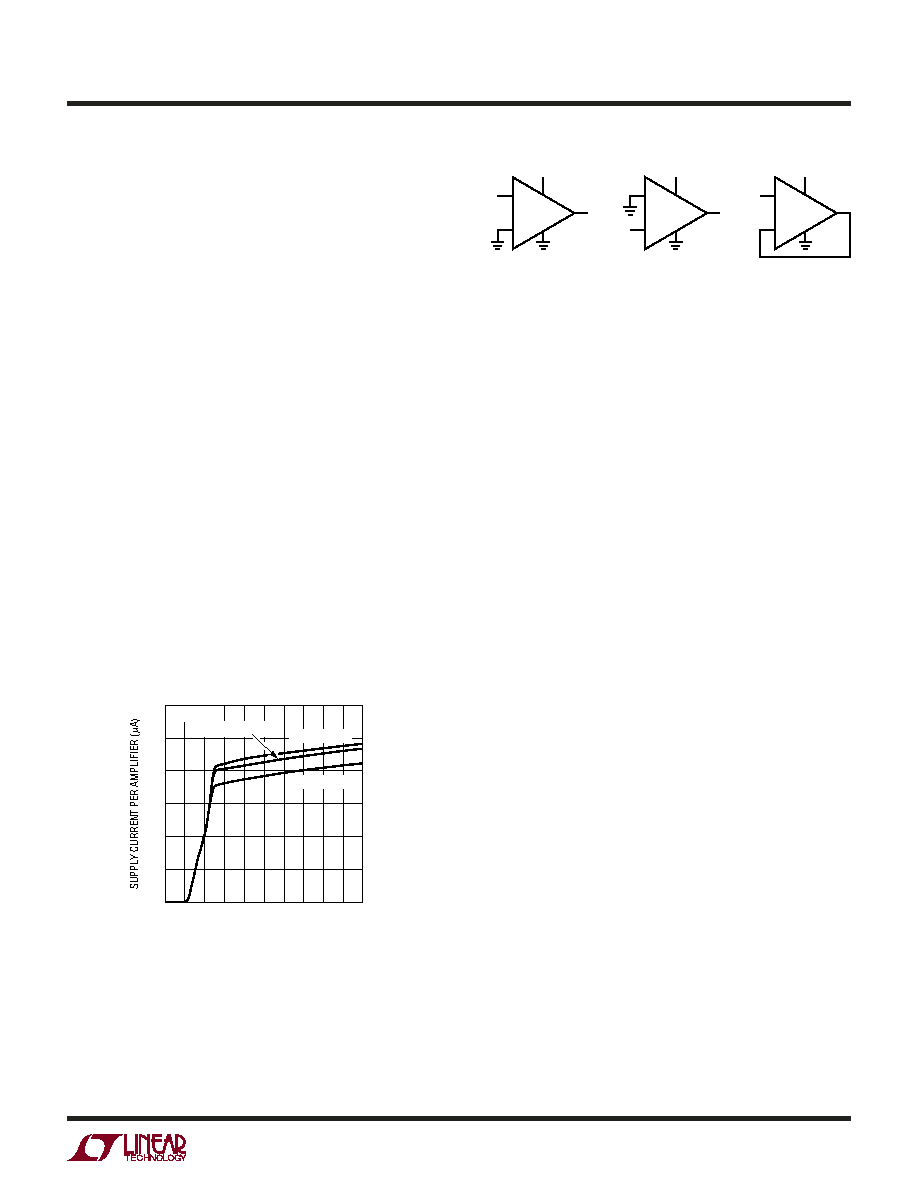 LT6003/LT6004/LT6005 15 600345f APPLICATIONS INFORMATION Gain The open-loop gain is almost independent of load when the output is sourcing current. This optimizes performance in single supply applications where the load is returned to ground. The typical performance curve of Open-Loop Gain for various loads shows the details. Start-Up and Output Saturation Characteristics Micropower op amps are often not micropower during start-up or during output saturation. This can wreak havoc on limited current supplies, in the worst case there may not be enough supply current available to take the system up to nominal voltages. Unlike the LT6003/LT6004/LT6005, when the output saturates, some op amps may draw excessive current and pull down the supplies, compromis- ing rail-to-rail performance. Figure 2 shows the start-up characteristics of the LT6003/LT6004/LT6005 for three limiting cases. The circuits are shown in Figure 3. One circuit creates a positive offset forcing the output to come up saturated high. Another circuit creates a negative offset forcing the output to come up saturated low, while the last circuit brings the output up at 1/2 supply. In all cases, the supply current is well controlled and is not excessive when the output is on either rail. Adaptive Filter The circuit of Figure 4 shows the LT6005 applied as a micropower adaptive filter, which automatically adjusts the time constant depending on the signal level. Op amp A1 buffers the input onto the RC which has either a 1ms or 20ms time constant depending on the state of switch S1. The signal is then buffered to the output by op amp A2. Op amps A3 and A4 are configured as gain-of-40 difference amplifiers, gaining up the difference between the buffered input voltage and the output. When there is no difference, the outputs of A3 and A4 will be near zero. When a positive signal step is applied to the input, the output of A3 rises. When a negative signal step is applied to the input, the output of A4 rises. These voltages are fed to the LT6700-2 comparator which has a built in 400mV reference. If the input step exceeds 10mV, the output of the difference amplifiers will exceed 400mV and the comparator output (wired in OR gate fashion) falls low. This turns on S1, reducing the time constant and speed- ing up the settling. The overall effect is that the circuit provides “slow filtering” with “fast settling”. Waveforms are shown in the accompanying photo, for a 100mV input step. The fast 1ms time constant is obvious in the output waveform, while the slow time constant is discernible as the slow ramping sections. That the slow time constant is discernible at all is due to delay time in the difference amplifier and comparator functions. Figure 2. Start-Up Characteristics SUPPLY VOLTAGE (V) 0 1.2 4 600345 F02 1.0 0.8 0.6 0.4 0.2 0 1 0.5 2 1.5 3 3.5 4.5 2.5 5 OUTPUT LOW OUTPUT HIGH OUTPUT AT VS/2 TA = 25°C Figure 3. Circuits for Start-Up Characteristics – + 30mV VS Output High – + VS/2 VS 600345 F03 Output at VS/2 – + 30mV VS Output Low |
|
|
Enlace URL |
| ¿ALLDATASHEET es útil para Ud.? [ DONATE ] |
Todo acerca de Alldatasheet | Publicidad | Contáctenos | Política de Privacidad | Enlace a la hoja de datos | Intercambio de Enlaces | Lista de Fabricantes All Rights Reserved©Alldatasheet.com |
| Russian : Alldatasheetru.com | Korean : Alldatasheet.co.kr | Spanish : Alldatasheet.es | French : Alldatasheet.fr | Italian : Alldatasheetit.com Portuguese : Alldatasheetpt.com | Polish : Alldatasheet.pl | Vietnamese : Alldatasheet.vn Indian : Alldatasheet.in | Mexican : Alldatasheet.com.mx | British : Alldatasheet.co.uk | New Zealand : Alldatasheet.co.nz |
|
Family Site : ic2ic.com |
icmetro.com |
 Mexican ▼
 English
 Chinese
 German
 Japanese
 Russian
 Korean
 Spanish
 French
 Italian
 Portuguese
 Polish
 Vietnamese
 Indian
 Mexican
 British
 New Zealand