|
Motor de Búsqueda de Datasheet de Componentes Electrónicos |
|
|
Motor de Búsqueda de Datasheet de Componentes Electrónicos |
|
LTC1707 Datasheet(PDF) 10 Page - Linear Technology |
|
|
|||||||||||||||||||||||||||||
LTC1707 Datasheet(HTML) 10 Page - Linear Technology |
|
|
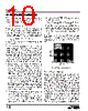
10 / 16 page  10 LTC1707 D1 in Figure 5 reduces the start delay but allows CSS to ramp up slowly providing the soft-start function. This diode can be deleted if soft-start is not needed. Efficiency Considerations The efficiency of a switching regulator is equal to the output power divided by the input power times 100%. It is often useful to analyze individual losses to determine what is limiting the efficiency and which change would produce the most improvement. Efficiency can be expressed as: Efficiency = 100% – (L1 + L2 + L3 + ...) where L1, L2, etc. are the individual losses as a percentage of input power. Although all dissipative elements in the circuit produce losses, two main sources usually account for most of the losses in LTC1707 circuits: VIN quiescent current and I2R losses. The VIN quiescent current loss dominates the efficiency loss at very low load currents whereas the I2R loss dominates the efficiency loss at medium to high load currents. In a typical efficiency plot, the efficiency curve at very low load currents can be misleading since the actual power lost is of no consequence as illustrated in Figure 6. 1. The VIN quiescent current is due to two components: the DC bias current as given in the electrical characteristics and the internal main switch and synchronous switch gate charge currents. The gate charge current results from switching the gate capacitance of the internal power MOSFET switches. Each time the gate is switched from high to low or from low to high, a packet of charge dQ moves from VIN to ground. The resulting dQ/dt is the current out of VINthat is typically larger than the DC bias current. In continuous mode, IGATECHG=f(QT+QB)where QT and QB are the gate charges of the internal top and bottom switches. Both the DC bias and gate charge losses are proportional to VIN and thus their effects will be more pronounced at higher supply voltages. 2. I2R losses are calculated from the resistances of the internal switches RSW and external inductor RL. In continuous mode the average output current flowing through inductor L is “chopped” between the main switch and the synchronous switch. Thus, the series resistance looking into SW pin from L is a function of both top and bottom MOSFET RDS(ON) and the duty cycle (DC) as follows: RSW = (RDS(ON)TOP)(DC) + (RDS(ON)BOT)(1 – DC) The RDS(ON) for both the top and bottom MOSFETs can be obtained from the Typical Performance Characteris- tics curves. Thus, to obtain I2R losses, simply add RSW to RL and multiply by the square of the average output current. Other losses including CIN and COUT ESR dissipative losses, MOSFET switching losses and inductor core and copper losses generally account for less than 2% total additional loss. Checking Transient Response The regulator loop response can be checked by looking at the load transient response. Switching regulators take several cycles to respond to a step in load current. When a load step occurs, VOUT immediately shifts by an amount equal to ( ∆ILOAD • ESR), where ESR is the effective series resistance of COUT. ∆ILOAD also begins to charge or dis- charge COUT, which generates a feedback error signal. The regulator loop then acts to return VOUT to its steady-state value. During this recovery time, VOUT can be monitored for overshoot or ringing that would indicate a stability problem. The internal compensation provides adequate compensation for most applications. But if additional compensation is required, the ITH pin can be used for external compensation as shown in Figure 7 (the 47pF capacitor, CC2, is typically needed for noise decoupling). LOAD CURRENT (mA) 1 0.001 0.01 0.1 1 10 100 1000 1707 F06 VOUT = 1.5V VOUT = 3.3V VOUT = 5V VIN = 6V Figure 6. Power Lost vs Load Current APPLICATIO S I FOR ATIO |
|
|
Enlace URL |
| ¿ALLDATASHEET es útil para Ud.? [ DONATE ] |
Todo acerca de Alldatasheet | Publicidad | Contáctenos | Política de Privacidad | Enlace a la hoja de datos | Intercambio de Enlaces | Lista de Fabricantes All Rights Reserved©Alldatasheet.com |
| Russian : Alldatasheetru.com | Korean : Alldatasheet.co.kr | Spanish : Alldatasheet.es | French : Alldatasheet.fr | Italian : Alldatasheetit.com Portuguese : Alldatasheetpt.com | Polish : Alldatasheet.pl | Vietnamese : Alldatasheet.vn Indian : Alldatasheet.in | Mexican : Alldatasheet.com.mx | British : Alldatasheet.co.uk | New Zealand : Alldatasheet.co.nz |
|
Family Site : ic2ic.com |
icmetro.com |
 Mexican ▼
 English
 Chinese
 German
 Japanese
 Russian
 Korean
 Spanish
 French
 Italian
 Portuguese
 Polish
 Vietnamese
 Indian
 Mexican
 British
 New Zealand