 |
Motor de Búsqueda de Datasheet de Componentes Electrónicos |
|
|
Motor de Búsqueda de Datasheet de Componentes Electrónicos |
|
MJE13003-R Datasheet(PDF) 6 Page - Unisonic Technologies |
|
|
|||||||||||||||||||||||||||||
MJE13003-R Datasheet(HTML) 6 Page - Unisonic Technologies |
|
|
6 / 8 page 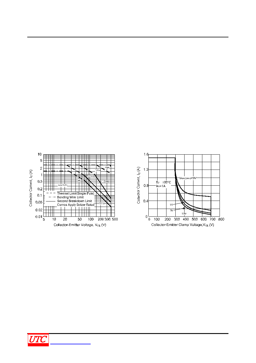 MJE13003-R NPN SILICON TRANSISTOR UNISONICTECHNOLOGIESCO.,LTD 6 of 8 www.unisonic.com.tw QW-R221-022.A SAFE OPERATING AREA INFORMATION FORWARD BIAS There are two limitations on the power handling ability of a transistor: average junction temperature and second breakdown. Safe operating area curves indicate IC-VCE limits of the transistor that must be observed for reliable operation; i.e., the transistor must not be subjected to greater dissipation than the curves indicate. The data of Fig.5 is based on TC = 25°C; TJ(PK) is variable depending on power level. Second breakdown pulse limits are valid for duty cycles to 10% but must be derated when TC≥25°C. Second breakdown limitations do not derate the same as thermal limitations. Allowable current at the voltages shown on Fig.5. TJ(PK) may be calculated from the data in Fig.4. At high case temperatures, thermal limitations will reduce the power that can be handled to values less than the limitations imposed by second breakdown. REVERSE BIAS For inductive loads, high voltage and high current must be sustained simultaneously during turn-off, in most cases, with the base to emitter junction reverse biased. Under these conditions the collector voltage must be held to a safe level at or below a specific value of collector current. This can be accomplished by several means such as active clamping, RC snubbing, load line shaping, etc. The safe level for these devices is specified as RBSOA( Reverse Bias Safe Operating Area) and represents the voltage-current conditions during reverse biased turn-off. This rating is verified under clamped conditions so that the device is never subjected to an avalanche mode. Fig.6 gives RBSOA characteristics. The Safe Operating Area of Fig.5 and 6 are specified ratings (for these devices under the test conditions shown.) Fig.5 Active Region Safe Operating Area Fig.6 Reverse Bias Safe Operating Area |
|
|
Enlace URL |
| ¿ALLDATASHEET es útil para Ud.? [ DONATE ] |
Todo acerca de Alldatasheet | Publicidad | Contáctenos | Política de Privacidad | Enlace a la hoja de datos | Intercambio de Enlaces | Lista de Fabricantes All Rights Reserved©Alldatasheet.com |
| Russian : Alldatasheetru.com | Korean : Alldatasheet.co.kr | Spanish : Alldatasheet.es | French : Alldatasheet.fr | Italian : Alldatasheetit.com Portuguese : Alldatasheetpt.com | Polish : Alldatasheet.pl | Vietnamese : Alldatasheet.vn Indian : Alldatasheet.in | Mexican : Alldatasheet.com.mx | British : Alldatasheet.co.uk | New Zealand : Alldatasheet.co.nz |
|
Family Site : ic2ic.com |
icmetro.com |
 Mexican ▼
 English
 Chinese
 German
 Japanese
 Russian
 Korean
 Spanish
 French
 Italian
 Portuguese
 Polish
 Vietnamese
 Indian
 Mexican
 British
 New Zealand


