|
Motor de Búsqueda de Datasheet de Componentes Electrónicos |
|
|
Motor de Búsqueda de Datasheet de Componentes Electrónicos |
|
TC7129CLW Datasheet(PDF) 11 Page - Microchip Technology |
|
|
|||||||||||||||||||||||||||||
TC7129CLW Datasheet(HTML) 11 Page - Microchip Technology |
|
|
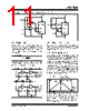
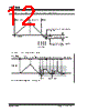
11 / 24 page  © 2002 Microchip Technology Inc. DS21459B-page 11 TC7129 FIGURE 4-6: TEMPERATURE COMPENSATING CIRCUITS 4.8 RC Oscillator For applications in which 3-1/2 digit (100 µV) resolution is sufficient, an RC oscillator is adequate. A recom- mended value for the capacitor is 51pF. Other values can be used as long as they are sufficiently larger than the circuit parasitic capacitance. The resistor value is calculated as: EQUATION 4-1: For 120kHz frequency and C = 51pF, the calculated value of R is 75k Ω. The RC oscillator and the crystal oscillator circuits are shown in Figure 4-7. FIGURE 4-7: OSCILLATOR CIRCUITS 4.9 Measuring Techniques Two important techniques are used in the TC7129: suc- cessive integration and digital auto-zeroing. Succes- sive integration is a refinement to the traditional dual slope conversion technique. 4.10 Dual Slope Conversion A dual slope conversion has two basic phases: inte- grate and de-integrate. During the integrate phase, the input signal is integrated for a fixed period of time; the integrated voltage level is thus proportional to the input voltage. During the de-integrate phase, the integrated voltage is ramped down at a fixed slope, and a counter counts the clock cycles until the integrator voltage crosses zero. The count is a measurement of the time to ramp the integrated voltage to zero, and is, there- fore, proportional to the input voltage being measured. This count can then be scaled and displayed as a mea- surement of the input voltage. Figure 4-8 shows the phases of the dual slope conversion. FIGURE 4-8: DUAL SLOPE CONVERSION The dual slope method has a fundamental limitation. The count can only stop on a clock cycle, so that mea- surement accuracy is limited to the clock frequency. In addition, a delay in the zero crossing comparator can add to the inaccuracy. Figure 4-9 shows these errors in an actual measurement. TC7129 1N4148 5k Ω 75k Ω 200k Ω 39k Ω 19 36 24 23 V- V+ VDISP DGND TC7129 2N2222 39k Ω 19 36 24 23 V- V+ VDISP DGND 20k Ω 18k Ω R= 0.45 Freq * C TC7129 TC7129 1 40 2 270k Ω 10pF V+ 120kHz 5pF V+ 1 40 2 51pF 75k Ω De-integrate Zero Crossing Time Integrate |
|
|
Enlace URL |
| ¿ALLDATASHEET es útil para Ud.? [ DONATE ] |
Todo acerca de Alldatasheet | Publicidad | Contáctenos | Política de Privacidad | Enlace a la hoja de datos | Intercambio de Enlaces | Lista de Fabricantes All Rights Reserved©Alldatasheet.com |
| Russian : Alldatasheetru.com | Korean : Alldatasheet.co.kr | Spanish : Alldatasheet.es | French : Alldatasheet.fr | Italian : Alldatasheetit.com Portuguese : Alldatasheetpt.com | Polish : Alldatasheet.pl | Vietnamese : Alldatasheet.vn Indian : Alldatasheet.in | Mexican : Alldatasheet.com.mx | British : Alldatasheet.co.uk | New Zealand : Alldatasheet.co.nz |
|
Family Site : ic2ic.com |
icmetro.com |
 Mexican ▼
 English
 Chinese
 German
 Japanese
 Russian
 Korean
 Spanish
 French
 Italian
 Portuguese
 Polish
 Vietnamese
 Indian
 Mexican
 British
 New Zealand