|
Motor de Búsqueda de Datasheet de Componentes Electrónicos |
|
|
Motor de Búsqueda de Datasheet de Componentes Electrónicos |
|
TC7129CLW Datasheet(PDF) 16 Page - Microchip Technology |
|
|
|||||||||||||||||||||||||||||
TC7129CLW Datasheet(HTML) 16 Page - Microchip Technology |
|
|
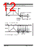
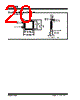
16 / 24 page  TC7129 DS21459B-page 16 © 2002 Microchip Technology Inc. FIGURE 4-15: DIGITAL GROUND (DGND) AND COMMON OUTPUTS 4.17 Low Battery The low battery annunciator turns on when supply volt- age between V- and V+ drops below 6.8V. The internal zener has a threshold of 6.3V. When the supply voltage drops below 6.8V, the transistor tied to V- turns OFF, pulling the "Low Battery" point HIGH. 4.18 Sequence and Results Counter A sequence counter and associated control logic pro- vide signals that operate the analog switches in the integrator section. The comparator output from the inte- grator gates the results counter. The results counter is a six-section up/down decade counter, which holds the intermediate results from each successive integration. 4.19 Over Range and Under Range Outputs When the results counter holds a value greater than ±19,999, the DP4/OR output (Pin 20) is driven HIGH. When the results counter value is less than ±1000, the DP3/UR output (Pin 21) is driven HIGH. Both signals are valid on the falling edge of LATCH/HOLD (L/H) and do not change until the end of the next conversion cycle. The signals are updated at the end of each con- version, unless the L/H input (Pin 22) is held HIGH. Pins 20 and 21 can also be used as inputs for external control of decimal points 3 and 4. Figure 4-14 shows a schematic of the input/output nature of these pins. 4.20 LATCH/Hold The L/H output goes LOW during the last 100 cycles of each conversion. This pulse latches the conversion data into the display driver section of the TC7129. This pin can also be used as an input. When driven HIGH, the display will not be updated; the previous reading is displayed. When driven LOW, the display reading is not latched; the sequence counter reading will be dis- played. Since the counter is counting much faster than the backplanes are being updated, the reading shown in this mode is somewhat erratic. 4.21 Display Driver TheTC7129drivesatriplexedLCD with threeback- planes. The LCD can include decimal points, polarity sign, and annunciators for continuity and low battery. Figure 4-16 shows the assignment of the display seg- ments to the backplanes and segment drive lines. The backplane drive frequency is obtained by dividing the oscillator frequency by 1200. This results in a back- plane drive frequency of 100Hz for 60Hz operation (120kHz crystal) and 83.3Hz for 50Hz operation (100kHz crystal). Backplane waveforms are shown in Figure 4-17. These appear on outputs BP1,BP2,BP3 (Pins 16, 17, and 18). They remain the same, regardless of the seg- ments being driven. Other display output lines (Pins 4 through 15) have waveforms that vary depending on the displayed val- ues. Figure 4-18 shows a set of waveforms for the A, G, D outputs (Pins 5, 8, 11, and 14) for several combina- tions of "ON" segments. The ANNUNCIATOR DRIVE output (Pin 3) is a square wave, running at the backplane frequency (100Hz or 83.3Hz) with a peak-to-peak voltage equal to DGND voltage. Connecting an annunciator to Pin 3 turns it ON; connecting it to its backplane turns it OFF. + – 12 µA P TC7129 Logic Section 5V 3.2V N N V+ V- COM DGND 24 28 36 23 |
|
|
Enlace URL |
| ¿ALLDATASHEET es útil para Ud.? [ DONATE ] |
Todo acerca de Alldatasheet | Publicidad | Contáctenos | Política de Privacidad | Enlace a la hoja de datos | Intercambio de Enlaces | Lista de Fabricantes All Rights Reserved©Alldatasheet.com |
| Russian : Alldatasheetru.com | Korean : Alldatasheet.co.kr | Spanish : Alldatasheet.es | French : Alldatasheet.fr | Italian : Alldatasheetit.com Portuguese : Alldatasheetpt.com | Polish : Alldatasheet.pl | Vietnamese : Alldatasheet.vn Indian : Alldatasheet.in | Mexican : Alldatasheet.com.mx | British : Alldatasheet.co.uk | New Zealand : Alldatasheet.co.nz |
|
Family Site : ic2ic.com |
icmetro.com |
 Mexican ▼
 English
 Chinese
 German
 Japanese
 Russian
 Korean
 Spanish
 French
 Italian
 Portuguese
 Polish
 Vietnamese
 Indian
 Mexican
 British
 New Zealand