|
Motor de Búsqueda de Datasheet de Componentes Electrónicos |
|
|
Motor de Búsqueda de Datasheet de Componentes Electrónicos |
|
INA114 Datasheet(PDF) 8 Page - Texas Instruments |
|
|
|
|||||||||||||||||||||||||||||
INA114 Datasheet(HTML) 8 Page - Texas Instruments |
|
|
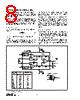
8 / 17 page  ® INA114 8 APPLICATION INFORMATION Figure 1 shows the basic connections required for operation of the INA114. Applications with noisy or high impedance power supplies may require decoupling capacitors close to the device pins as shown. The output is referred to the output reference (Ref) terminal which is normally grounded. This must be a low-impedance connection to assure good common-mode rejection. A resis- tance of 5 Ω in series with the Ref pin will cause a typical device to degrade to approximately 80dB CMR (G = 1). SETTING THE GAIN Gain of the INA114 is set by connecting a single external resistor, R G: Commonly used gains and resistor values are shown in Figure 1. The 50k Ω term in equation (1) comes from the sum of the two internal feedback resistors. These are on-chip metal film resistors which are laser trimmed to accurate absolute val- FIGURE 1. Basic Connections. G = 1 + 50 kΩ R G (1) DESIRED R G NEAREST 1% R G GAIN ( Ω)(Ω) 1 No Connection No Connection 2 50.00k 49.9k 5 12.50k 12.4k 10 5.556k 5.62k 20 2.632k 2.61k 50 1.02k 1.02k 100 505.1 511 200 251.3 249 500 100.2 100 1000 50.05 49.9 2000 25.01 24.9 5000 10.00 10 10000 5.001 4.99 ues. The accuracy and temperature coefficient of these resistors are included in the gain accuracy and drift specifi- cations of the INA114. The stability and temperature drift of the external gain setting resistor, RG, also affects gain. RG’s contribution to gain accuracy and drift can be directly inferred from the gain equation (1). Low resistor values required for high gain can make wiring resistance important. Sockets add to the wiring resistance which will contribute additional gain error (possi- bly an unstable gain error) in gains of approximately 100 or greater. NOISE PERFORMANCE The INA114 provides very low noise in most applications. For differential source impedances less than 1k Ω, the INA103 may provide lower noise. For source impedances greater than 50k Ω, the INA111 FET-input instrumentation ampli- fier may provide lower noise. Low frequency noise of the INA114 is approximately 0.4 µVp-p measured from 0.1 to 10Hz. This is approximately one-tenth the noise of “low noise” chopper-stabilized ampli- fiers. A 1 A 2 A 3 6 25k Ω 25k Ω 25k Ω 25k Ω 7 4 3 8 1 2 V IN V IN R G V+ V– INA114 G = 1 + 50k Ω R G – + 5 Over-Voltage Protection 25k Ω 25k Ω Over-Voltage Protection Load V O = G • (VIN – VIN) + – 0.1µF 0.1µF Pin numbers are for DIP packages. + – V O INA114 R G Also drawn in simplified form: V O Ref V IN – V IN + |
|
|
Enlace URL |
| ¿ALLDATASHEET es útil para Ud.? [ DONATE ] |
Todo acerca de Alldatasheet | Publicidad | Contáctenos | Política de Privacidad | Enlace a la hoja de datos | Intercambio de Enlaces | Lista de Fabricantes All Rights Reserved©Alldatasheet.com |
| Russian : Alldatasheetru.com | Korean : Alldatasheet.co.kr | Spanish : Alldatasheet.es | French : Alldatasheet.fr | Italian : Alldatasheetit.com Portuguese : Alldatasheetpt.com | Polish : Alldatasheet.pl | Vietnamese : Alldatasheet.vn Indian : Alldatasheet.in | Mexican : Alldatasheet.com.mx | British : Alldatasheet.co.uk | New Zealand : Alldatasheet.co.nz |
|
Family Site : ic2ic.com |
icmetro.com |
 Mexican ▼
 English
 Chinese
 German
 Japanese
 Russian
 Korean
 Spanish
 French
 Italian
 Portuguese
 Polish
 Vietnamese
 Indian
 Mexican
 British
 New Zealand