|
Motor de Búsqueda de Datasheet de Componentes Electrónicos |
|
|
Motor de Búsqueda de Datasheet de Componentes Electrónicos |
|
LTM4650 Datasheet(PDF) 8 Page - Analog Devices |
|
|
|||||||||||||||||||||||||||||
LTM4650 Datasheet(HTML) 8 Page - Analog Devices |
|
|
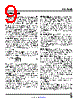
8 / 28 page  LTM4660 8 Rev. 0 For more information www.analog.com PIN FUNCTIONS VOUT (A1-3, B1-3, C1-3, D1-3, E3, F3, G3, H3): Output Voltage. Bypass to ground with capacitors appropriate for the application. See Decoupling Requirements. VIN (A5, B5, C5, D5, E5): Main Input Supply. Bypass this pin to GND with at least 2 × 4.7µF X7R- or X7S-type capacitors with appropriate voltage rating. C+ (A6, B6, C6, D6, E6, F6, G5-6, H5-6, J6, K6, L6, M6): Switch Node Connection to One Terminal of Flying Capacitor. Voltage at this pin swings between VIN/2 and VIN. C– (A8-11, B8-11, C8-11, D8, E8, F8, G8, H8, J8, K8, L8, M8): Switch Node Connection to Internal Power Inductor and One Terminal of Flying Capacitor. Voltage at this pin swings between ground and VIN/2. GND (A12, B12, C12, D9-D12, E9-12, F9-12, G9, H9, J1-2, K1-2, L1-2, M1): Power Ground. Connect all mod- ule GND pins to the application’s power ground plane. MID (E1-2, F1-2, G1-2, G10-12, H1, H10-12, J10-12): Half Supply from VIN. Do not use this to source current. Connect MLCC bypass capacitors from this node to GND. A minimum of 8 × 10µF X7R or X7S MLCC capacitors is recommended. Higher efficiency can be achieved with 12 × 10µF X7R or X7S MLCC capacitors. All MID pins are internally connected within the module, but in order for the LTM4660 to achieve the best possible efficiency, it is necessary to connect all MID pins together with large cop- per plane(s) external to the module. See the Applications Information section. VINSNS (F5): VIN Kelvin Sensing Input. Used to accurately sense input voltage. Connect to VIN, under the module. MIDSNS (H2): MID Kelvin Sensing Input. Used to accurately sense MID voltage. Connect to MID under the module. FAULT (J3): Open Drain Output pin. When the signal goes low, it indicates one of the following conditions: a. In the capacitor balancing phase, capacitors CFLY or CMID (see Typical Applications) are not charged to VIN/2. A low FAULT indicates an abnormal condition that is preventing CFLY or CMID from being be charged up to VIN/2. b. During normal operation, the voltage deviates from VIN/2 by a window amount set by the voltage on the HYS_PRGM pin. c. The die temperature exceeds its internally set limit or the PTC resistor connected as the lower leg of a resistor divider (if used) trips the TEMP pin threshold. During any of the aforementioned conditions, the TRACK/ SS pin will also be pulled low. INTVCC (J4): Internal Regulator Output. Powers control circuits and gate drivers internal to the module. Leave this pin floating. TEMP+ (J9): Temperature Sensor, Positive Input. Emitter of a 2N3906-genre PNP bipolar junction transistor (BJT). Optionally interface to temperature monitoring circuitry such as LTC®2997, LTC2990, LTC2974 or LTC2975. Otherwise leave electrically open. TEMP– (K9): Temperature Sensor, Negative Input. Collector-base of a 2N3906-genre PNP bipolar junction transistor (BJT). Optionally interface to temperature mon- itoring circuitry such as LTC2997, LTC2990, LTC2974 or LTC2975. Otherwise leave electrically open. TIMER (K3): Charge Balancing Timer Input. A capaci- tor connected from this pin to SGND sets the amount of time allocated to charge CFLY and CMID to VIN/2 during the capacitor balancing phase. It also sets the auto-retry timeout, should the capacitors fail to reach this voltage within the set time. Capacitors CFLY and CMID begin and end charging when the TIMER voltage is between 0.5V and 1.2V, respectively. If the capacitor is balanced before the TIMER voltage reaches 1.2V, this voltage is reset to ground and normal operation begins. However, if the bal- ance is not reached when the voltage reaches 1.2V, then the charging of the capacitors stops and the auto-retry timeout period begins. The TIMER capacitor will now slew at half the rate until it reaches 4V and then resets to zero and begins to slew at 1× rate. Once it reaches 0.5V, the CFLY and CMID begin to charge again and the process repeats. TEST (K4): Test Pin. Used in ATE test, only. Leave open circuit. |
|
Enlace URL |
| ¿ALLDATASHEET es útil para Ud.? [ DONATE ] |
Todo acerca de Alldatasheet | Publicidad | Contáctenos | Política de Privacidad | Enlace a la hoja de datos | Intercambio de Enlaces | Lista de Fabricantes All Rights Reserved©Alldatasheet.com |
| Russian : Alldatasheetru.com | Korean : Alldatasheet.co.kr | Spanish : Alldatasheet.es | French : Alldatasheet.fr | Italian : Alldatasheetit.com Portuguese : Alldatasheetpt.com | Polish : Alldatasheet.pl | Vietnamese : Alldatasheet.vn Indian : Alldatasheet.in | Mexican : Alldatasheet.com.mx | British : Alldatasheet.co.uk | New Zealand : Alldatasheet.co.nz |
|
Family Site : ic2ic.com |
icmetro.com |
 Mexican ▼
 English
 Chinese
 German
 Japanese
 Russian
 Korean
 Spanish
 French
 Italian
 Portuguese
 Polish
 Vietnamese
 Indian
 Mexican
 British
 New Zealand