|
Motor de Búsqueda de Datasheet de Componentes Electrónicos |
|
|
Motor de Búsqueda de Datasheet de Componentes Electrónicos |
|
LTM4650 Datasheet(PDF) 9 Page - Analog Devices |
|
|
|||||||||||||||||||||||||||||
LTM4650 Datasheet(HTML) 9 Page - Analog Devices |
|
|
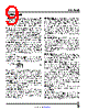
9 / 28 page  LTM4660 9 Rev. 0 For more information www.analog.com PIN FUNCTIONS EXTVCC (K10): External Power Input to an Internal LDO Connected to INTVCC. This LDO supplies INTVCC power, bypassing the internal LDO powered from VIN whenever EXTVCC is higher than 8V. Do not float or exceed 20V on this pin. Connect EXTVCC to GND, if the features is unused. To reduce internal module temperature rise, it is strongly recommended to bias EXTVCC with 8VDC or higher. For applications where VOUT ≥ 8V, there is an easy way: con- nect VOUT to EXTVCC. For applications where VOUT < 8V, it is strongly recommended to drive EXTVCC to 8V (or higher) with an external bias supply. When driving EXTVCC exter- nally, take precautions to ensure EXTVCC ≤ VIN at all times. TEMP (K11): Temperature Sensing Input. Using a PTC resistor as the lower leg of a resistor divider, connect the TEMP pin to the common point of the divider. The PTC resistor is used to monitor a hot spot on the PCB. Once it reaches the TEMP threshold of 1.22V, the LTM4660 stops switching for 100ms before retrying. Ground this pin if not used. VFB (K12): Error Amplifier Feedback Input. Connect resis- tor RVFB from this pin to SGND in order to configure the VOUT output voltage setting. RVFB is given by Equation 1. RVFB (kΩ) = 60.4 VOUT VVFB − 1 ⎛ ⎝⎜ ⎞ ⎠⎟ (1) When EXT_REF is connected to INTVCC, the module regu- lates the VFB pin at 0.8V, nominal. If EXT_REF is used or TRACK/SS is externally driven to influence the VFB tar- get servo voltage, the value of RVFB must be computed accordingly. (See the Applications Information section.) RUN (L3): Run Control Input. A voltage above 1.3V turns the LTM4660 ON. A voltage below 1.1V causes the mod- ule to shutdown. There is a 1μA pull-up current on this pin when its voltage is below 1.3V. SGND (L4, L12, M12): Signal Ground. All small-signal components and compensation components (if used) should connect to this signal SGND, which connects to GND internal to the module. It is not necessary to connect SGND to GND externally. TRACK/SS (L9): Output Voltage Tracking and Soft-Start Input. The LTM4660 regulates the VFB voltage to the low- est of three voltages: 0.8V, the voltage on the EXT_REF pin or the voltage on the TRACK/SS pin. An internal 10μA pull-up current source is connected to this pin. A capaci- tor to SGND at this pin sets the ramp time to the final regulated output voltage. Alternatively, a resistor divider from another voltage supply connected to this pin allows the LTM4660 output voltage to track the other supply during start-up. HYS_PRGM (L11): There is a 10μA current flowing out of this pin. A voltage created by connecting a resistor from this pin to SGND sets an equal amount of window threshold around VIN/2 to a window comparator. When the voltage at MIDSNS is not within this window threshold, FAULT will be pulled low and switching will stop. CFLY and CMID will be rebalanced to half of VIN before resuming normal operation. PGOOD (M2): Power Good Pin. This is an open drain output. PGOOD is pulled to ground when voltage at VFB pin falls below 7.5% or rises above 8.5% of its set point. It will also be pulled low when FAULT is tripped. MODE/PLLIN (M3): Mode Selection or External Synchronization Input to Phase Detector. When external synchronization is not used, this pin selects the operating modes and can be tied to SGND, to INTVCC or left open circuit. If the pin is connected to SGND, it enables forced continuous mode while a connection to INTVCC enables pulse-skipping mode. Floating the pin enables Burst Mode operation. For external sync, apply a clock signal to this pin. The integrated PLL along with its internal compen- sation network will synchronize the internal oscillator to external clock. Forced continuous mode will be enabled when an external clock is applied. CLKOUT (M4): Clock Output Pin. This pin outputs a clock 180° out of phase with the main operating clock of the LTM4660. EXT_REF (M9): External Reference Input. A voltage applied to this pin forces the VFB to regulate to this volt- age. Internal clamps set at 0.45V and 0.9V limit the lower and upper bounds of VFB regulation that EXT_REF can |
|
Enlace URL |
| ¿ALLDATASHEET es útil para Ud.? [ DONATE ] |
Todo acerca de Alldatasheet | Publicidad | Contáctenos | Política de Privacidad | Enlace a la hoja de datos | Intercambio de Enlaces | Lista de Fabricantes All Rights Reserved©Alldatasheet.com |
| Russian : Alldatasheetru.com | Korean : Alldatasheet.co.kr | Spanish : Alldatasheet.es | French : Alldatasheet.fr | Italian : Alldatasheetit.com Portuguese : Alldatasheetpt.com | Polish : Alldatasheet.pl | Vietnamese : Alldatasheet.vn Indian : Alldatasheet.in | Mexican : Alldatasheet.com.mx | British : Alldatasheet.co.uk | New Zealand : Alldatasheet.co.nz |
|
Family Site : ic2ic.com |
icmetro.com |
 Mexican ▼
 English
 Chinese
 German
 Japanese
 Russian
 Korean
 Spanish
 French
 Italian
 Portuguese
 Polish
 Vietnamese
 Indian
 Mexican
 British
 New Zealand