|
Motor de Búsqueda de Datasheet de Componentes Electrónicos |
|
|
Motor de Búsqueda de Datasheet de Componentes Electrónicos |
|
STM32H7B3AI Datasheet(PDF) 141 Page - STMicroelectronics |
|
|
|||||||||||||||||||||||||||||
STM32H7B3AI Datasheet(HTML) 141 Page - STMicroelectronics |
|
|
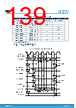
141 / 238 page  6.3.19 Octo-SPI interface characteristics Unless otherwise specified, the parameters given in Table 90. OCTOSPI characteristics in SDR mode and Table 91. OCTOSPI characteristics in DTR mode (with DQS)/Octal and Hyperbus for the OCTOSPI interface are derived from tests performed under the ambient temperature, fHCLK frequency and VDD supply voltage summarized in Table 22. General operating conditions, with the following configuration: • Output speed is set to OSPEEDRy[1:0] = 11 • Measurement points are done at CMOS levels: 0.5VDD • I/O compensation cell activated. • HSLV activated when VDD ≤ 2.7 V • VOS level set to VOS0 Note: At VOS1, the performance can be degraded by up to 5 % compared to VOS0. This is indicated by a footnote when applicable. Refer to Section 6.3.16 I/O port characteristics for more details on the input/output alternate function characteristics. Table 90. OCTOSPI characteristics in SDR mode Delay block bypassed. Symbol Parameter Conditions Min(1)(2) Typ(1)(2) Max(1)(2)(3) Unit F(CLK) OCTOSPI clock frequency 1.62 V < VDD < 3.6 V, VOS0, CLOAD = 15 pF - - 90 MHz 1.62 V < VDD < 3.6 V, VOS0, CLOAD = 20 pF - - 80 2.7 V < VDD < 3.6 V, VOS0, CLOAD = 20 pF - - 140 tw(CLKH) OCTOSPI clock high and low time PRESCALER[7:0] = n = 0,1,3,5 t(CLK)/2 - t(CLK)/2+1 ns tw(CLKL) t(CLK)/2−1 - t(CLK)/2 tw(CLKH) OCTOSPI clock high and low time PRESCALER[7:0] = n = 2,4,6,8 (n/2)*t(CLK)/ (n+1) - (n/2)*t(CLK)/ (n+1)+1 tw(CLKL) (n/2+1)*t(CLK)/ (n+1) −1 - (n/2+1)*t(CLK)/ (n+1) ts(IN)(4) Data input setup time 2.7 V < VDD < 3.6 V 2 - - 1.62 V < VDD < 3.6 V 2 - - th(IN)(4) Data input hold time 2.7 V < VDD < 3.6 V 4.5 - - 1.62 V < VDD < 3.6 V 5 - - tv(OUT) Data output valid time - - 1 1.5(4) th(OUT) Data output hold time - 0 - - 1. All values apply to Octal and Quad-SPI mode. 2. Guaranteed by characterization results. 3. At VOS1, these values are degraded by up to 5 %. 4. Using PC2, PC3, PI11, PF0 or PF1 I/O in the data bus adds 3.5 ns to this timing value. STM32H7B3xI Operating conditions DS13139 - Rev 8 page 141/238 |
|
Enlace URL |
| ¿ALLDATASHEET es útil para Ud.? [ DONATE ] |
Todo acerca de Alldatasheet | Publicidad | Contáctenos | Política de Privacidad | Enlace a la hoja de datos | Intercambio de Enlaces | Lista de Fabricantes All Rights Reserved©Alldatasheet.com |
| Russian : Alldatasheetru.com | Korean : Alldatasheet.co.kr | Spanish : Alldatasheet.es | French : Alldatasheet.fr | Italian : Alldatasheetit.com Portuguese : Alldatasheetpt.com | Polish : Alldatasheet.pl | Vietnamese : Alldatasheet.vn Indian : Alldatasheet.in | Mexican : Alldatasheet.com.mx | British : Alldatasheet.co.uk | New Zealand : Alldatasheet.co.nz |
|
Family Site : ic2ic.com |
icmetro.com |
 Mexican ▼
 English
 Chinese
 German
 Japanese
 Russian
 Korean
 Spanish
 French
 Italian
 Portuguese
 Polish
 Vietnamese
 Indian
 Mexican
 British
 New Zealand