|
Motor de Búsqueda de Datasheet de Componentes Electrónicos |
|
|
Motor de Búsqueda de Datasheet de Componentes Electrónicos |
|
STM32H7B3II Datasheet(PDF) 169 Page - STMicroelectronics |
|
|
|||||||||||||||||||||||||||||
STM32H7B3II Datasheet(HTML) 169 Page - STMicroelectronics |
|
|
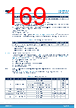
169 / 238 page  Symbol Parameter Condition Min Unit fI2CCLK I2CCLK frequency Fast-mode Plus Analog Filtre OFF, DNF=1 16 - The SDA and SCL I/O requirements are met with the following restrictions: • The SDA and SCL I/O pins are not “true” open-drain. When configured as open-drain, the PMOS connected between the I/O pin and VDDIOx is disabled, but still present. • The 20 mA output drive requirement in Fast-mode Plus is not supported. This limits the maximum load CLoad supported in Fm+, which is given by these formulas: tr(SDA/SCL)=0.8473xRPxCLoad RP(min)= (VDD-VOL(max))/IOL(max) Where RP is the I2C lines pull-up. Refer to Section 6.3.16 I/O port characteristics for the I2C I/Os characteristics. All I2C SDA and SCL I/Os embed an analog filter. Refer to the table below for the analog filter characteristics: Table 116. I2C analog filter characteristics Symbol Parameter Min(1) Max(1) Unit tAF Maximum pulse width of spikes that are suppressed by analog filter 50(2) 260(3) ns 1. Guaranteed by design. 2. Spikes whose width is lower than tAF(min) are filtered. 3. Spikes whose width is higer than tAF(max) are not filtered. 6.3.36.2 USART interface characteristics Unless otherwise specified, the parameters given in Table 117 for USART are derived from tests performed under the ambient temperature, fPCLKx frequency and VDD supply voltage conditions summarized in Table 22. General operating conditions and Section 6.3.1 , with the following configuration: • Output speed is set to OSPEEDRy[1:0] = 11 • Capacitive load CL = 30 pF • Measurement points are done at CMOS levels: 0.5VDD • IO Compensation cell activated. • VOS level set to VOS0 Note: At VOS1, the performance can be degraded by up to 5 % compared to VOS0. This is indicated by a footnote when applicable. Refer to Section 6.3.16 I/O port characteristics for more details on the input/output alternate function characteristics (NSS, CK, TX, RX for USART). Table 117. USART characteristics Symbol Parameter Conditions Min Typ Max(1) Unit fCK USART clock frequency Master mode - - 35 MHz Slave receiver mode 93.0 Slave mode transmitter mode, 2.7 V < VDD < 3.6 V 29.0 Slave mode transmitter mode, 1.62 V < VDD < 3.6 V 22.0 tsu(NSS) NSS setup time Slave mode tker+2 - - - th(NSS) NSS hold time Slave mode 2 - - tw(SCKH), tw(SCKL) CK high and low time Master mode 1/fck/2−2 1/fck/2 1/fck/2+2 tsu(RX) Data input setup time Master mode 17 - - ns Slave mode 1 - - STM32H7B3xI Operating conditions DS13139 - Rev 8 page 169/238 |
|
Enlace URL |
| ¿ALLDATASHEET es útil para Ud.? [ DONATE ] |
Todo acerca de Alldatasheet | Publicidad | Contáctenos | Política de Privacidad | Enlace a la hoja de datos | Intercambio de Enlaces | Lista de Fabricantes All Rights Reserved©Alldatasheet.com |
| Russian : Alldatasheetru.com | Korean : Alldatasheet.co.kr | Spanish : Alldatasheet.es | French : Alldatasheet.fr | Italian : Alldatasheetit.com Portuguese : Alldatasheetpt.com | Polish : Alldatasheet.pl | Vietnamese : Alldatasheet.vn Indian : Alldatasheet.in | Mexican : Alldatasheet.com.mx | British : Alldatasheet.co.uk | New Zealand : Alldatasheet.co.nz |
|
Family Site : ic2ic.com |
icmetro.com |
 Mexican ▼
 English
 Chinese
 German
 Japanese
 Russian
 Korean
 Spanish
 French
 Italian
 Portuguese
 Polish
 Vietnamese
 Indian
 Mexican
 British
 New Zealand