|
Motor de Búsqueda de Datasheet de Componentes Electrónicos |
|
|
Motor de Búsqueda de Datasheet de Componentes Electrónicos |
|
HS-82C54RH Datasheet(PDF) 9 Page - Renesas Technology Corp |
|
|
|||||||||||||||||||||||||||||
HS-82C54RH Datasheet(HTML) 9 Page - Renesas Technology Corp |
|
|
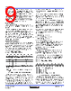
9 / 17 page  FN3043 Rev 2.00 Page 9 of 17 Aug 2000 HS-82C54RH A new initial count may be written to a Counter at any time without affecting the Counter’s programmed Mode in anyway. Counting will be affected as described in the Mode definitions. The new count must follow the programmed count format. If a Counter is programmed to read/write two-byte counts, the following precaution applies: A program must not transfer control between writing the first and second byte to another routine which also writes into that same Counter. Otherwise, the Counter will be loaded with an incorrect count. Read Operations It is often desirable to read the value of a Counter without disturbing the count in progress. This is easily done in the HS- 82C54RH. There are three possible methods for reading the Counters. The first is through the Read-Back Command, which is explained later. The second is a simple read operation of the Counter, which is selected with the A1, A0 inputs. The only requirement is that the CLK input of the selected Counter must be inhibited by using either the GATE input or external logic. Otherwise, the count may be in process of changing when it is read, giving an undefined result. Counter Latch Command The other method for reading the Counters involves a special software command called the “Counter Latch Command”. Like a Control Word, this command is written to the Control Word Register, which is selected when A1, A0 = 11. Also, like a Control Word, the SC0, SC1 bits select one of the three Counters, but two other bits, D5 and D4, distinguish this command from a Control Word. A1, A0 = 11; CS = 0; RD = 1; WR = 0 The selected Counter’s Output Latch (OL) latches the count when the Counter Latch Command is received. This count is held in the latch until it is read by the CPU (or until the Counter is reprogrammed). The count is then unlatched automatically and the OL returns to “following” the Counting Element (CE). This allows reading the contents of the Counters “on the fly” without affecting counting in progress. Multiple Counter Latch Commands may be used to latch more than one Counter. Each latched Counter’s OL holds its count until read. Counter Latch Commands do not affect the programmed Mode of the Counter in any way. If a Counter is latched and then, some time later, latched again before the count is read, the second Counter Latch Command is ignored. The count read will be the count at the time the first Counter Latch Command was issued. With either method, the count must be read according to the programmed format; specifically, if the Counter is programmed for two byte counts, two bytes must be read. The two bytes do not have to be read one right after the other; read or write or programming operations of other Counters may be inserted between them. Another feature of the HS-82C54RH is that reads and writes of the same Counter may be interleaved; for example, if the Counter is programmed for two byte counts, the following sequence is valid. 1. Read least significant byte. 2. Write new least significant byte. 3. Read most significant byte. 4. Write new most significant byte. If a Counter is programmed to read or write two-byte counts, the following precaution applies: A program MUST NOT transfer control between reading the first and second byte to another routine which also reads from that same Counter. Otherwise, an incorrect count will be read. Read-Back Command The Read-Back Command allows the user to check the count value, programmed Mode, and current state of the OUT pin and Null Count flag of the selected Counter(s). The command is written into the Control Word Register and has the format shown in Figure 12. The command applies to the Counters selected by setting their corresponding bits D3, D2, D1 = 1. A0, A1 = 11; CS = 0; RD = 1; WR = 0 The Read-Back Command may be used to latch multiple Counter Output Latches (OL) by setting the COUNT bit D5 = 0 and selecting the desired Counter(s). This single command is functionally equivalent to several Counter Latch Commands, one for each Counter latched. Each Counter’s latched count is held until it is read (or the Counter is reprogrammed). That D7 D6 D5 D4 D3 D2 D1 D0 SC1 SC0 0 0 X X X X SC1, SC0 - specify counter to be latched SC1 SC1 Counter 0 0 0 0 0 1 1 1 2 1 1 Read-Back Command D5, D4 = 00 designates Counter Latch Command X = Don’t Care NOTE: Don’t Care bits (X) should be 0 to insure compatibility with future products. FIGURE 11. COUNTER LATCH COMMAND FORMAT D7 D6 D5 D4 D3 D2 D1 D0 1 1 COUNT STATUS CNT 2 CNT 1 CNT 0 0 D5: 0 = Latch count of selected Counters(s) D4: 0 = Latch status of selected Counters(s) D3: 1 = Select Counter 2 D2: 1 = Select Counter 1 D1: 1 = Select Counter 0 D0: Reserved for future expansion; Must be 0 FIGURE 12. READ-BACK COMMAND FORMAT |
|
|
Enlace URL |
| ¿ALLDATASHEET es útil para Ud.? [ DONATE ] |
Todo acerca de Alldatasheet | Publicidad | Contáctenos | Política de Privacidad | Enlace a la hoja de datos | Intercambio de Enlaces | Lista de Fabricantes All Rights Reserved©Alldatasheet.com |
| Russian : Alldatasheetru.com | Korean : Alldatasheet.co.kr | Spanish : Alldatasheet.es | French : Alldatasheet.fr | Italian : Alldatasheetit.com Portuguese : Alldatasheetpt.com | Polish : Alldatasheet.pl | Vietnamese : Alldatasheet.vn Indian : Alldatasheet.in | Mexican : Alldatasheet.com.mx | British : Alldatasheet.co.uk | New Zealand : Alldatasheet.co.nz |
|
Family Site : ic2ic.com |
icmetro.com |
 Mexican ▼
 English
 Chinese
 German
 Japanese
 Russian
 Korean
 Spanish
 French
 Italian
 Portuguese
 Polish
 Vietnamese
 Indian
 Mexican
 British
 New Zealand