|
Motor de Búsqueda de Datasheet de Componentes Electrónicos |
|
|
Motor de Búsqueda de Datasheet de Componentes Electrónicos |
|
AT83EB5114 Datasheet(PDF) 13 Page - ATMEL Corporation |
|
|
|||||||||||||||||||||||||||||
AT83EB5114 Datasheet(HTML) 13 Page - ATMEL Corporation |
|
|
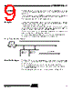
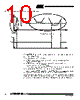
13 / 95 page  13 AT89/83EB5114 4311C–8051–02/08 Description The clock for the whole circuit and peripherals is first divided by two before being used by the CPU core and the peripherals. This allows any cyclic ratio to be accepted on XTAL1 input. In X2 mode, as this divider is bypassed, the signals on XTAL1 must have a cyclic ratio from 40 to 60%. Figure 4 shows the clock generation block diagram. X2 bit is validated on the rising edge of the XTAL1÷2 to avoid glitches when switching from X2 to standard mode. Figure 5 shows the switching mode waveforms. Figure 5. Mode Switching Waveforms The X2 bit in the CKCON register (see Table 7 on page 18) allows to switch from 12 clock periods per instruction to 6 clock periods and vice versa. Clock Prescaler Before supplying the CPU and the peripherals, the main clock is divided by a factor from 2 to 32, as defined by the CKRL register (see Table 6 on page 18). The CPU needs from 12 to 16*12 clock periods per instruction. This allows: • to accept any cyclic ratio on XTAL1 input. • to reduce CPU power consumption. Note: The number of bits of the prescaler is optimized in order to provide a low power con- sumption in low speed mode (see Section “Electrical Characteristics”, page 84). Prescaler Divider on Reset A hardware RESET selects the start oscillator depending on the RST1_OSC and RST0_OSC bits contained on the Hardware Security Byte register (see Table 2 on page 15). It also selects the prescaler divider as follows: • CKRL = 8h: internal clock = OscOut / 16 (slow CPU speed at reset, thus lower power consumption) • X2 = 0, • SEL_OSC1 and SEL_OSC0 bits selects OSCA, OSCB or OSCC, depending on the value of the RST_OSC1 and RST_OSC0 configuration bits. • After Reset, any value between Fh down to 0h can be written by software into CKRL sfr in order to divide frequency of the selected oscillator: – CKRL = 0h: minimum frequency = OscOut / 32 – CKRL = Fh: maximum frequency = OscOut / 2 The frequency of the CPU and peripherals clock CkOut is related to the frequency of the main oscillator OscOut by the following formula: FCkOut = FOscOut / (32 - 2*CKRL) XTAL1:2 XTAL1 CPU clock X2 bit X2 Mode STD Mode STD Mode FOSC |
|
Enlace URL |
| ¿ALLDATASHEET es útil para Ud.? [ DONATE ] |
Todo acerca de Alldatasheet | Publicidad | Contáctenos | Política de Privacidad | Enlace a la hoja de datos | Intercambio de Enlaces | Lista de Fabricantes All Rights Reserved©Alldatasheet.com |
| Russian : Alldatasheetru.com | Korean : Alldatasheet.co.kr | Spanish : Alldatasheet.es | French : Alldatasheet.fr | Italian : Alldatasheetit.com Portuguese : Alldatasheetpt.com | Polish : Alldatasheet.pl | Vietnamese : Alldatasheet.vn Indian : Alldatasheet.in | Mexican : Alldatasheet.com.mx | British : Alldatasheet.co.uk | New Zealand : Alldatasheet.co.nz |
|
Family Site : ic2ic.com |
icmetro.com |
 Mexican ▼
 English
 Chinese
 German
 Japanese
 Russian
 Korean
 Spanish
 French
 Italian
 Portuguese
 Polish
 Vietnamese
 Indian
 Mexican
 British
 New Zealand