|
Motor de Búsqueda de Datasheet de Componentes Electrónicos |
|
|
Motor de Búsqueda de Datasheet de Componentes Electrónicos |
|
AD7013 Datasheet(PDF) 5 Page - Analog Devices |
|
|
|||||||||||||||||||||||||||||
AD7013 Datasheet(HTML) 5 Page - Analog Devices |
|
|
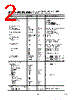
5 / 20 page  REV. A AD7013 –5– PIN FUNCTION DESCRIPTIONS SSOP Pin Number Mnemonic Function POWER SUPPLY 1V AA Positive Power Supply for Analog section. A 0.1 µF decoupling capacitor should be connected between this pin and AGND. 21 V DD Positive Power Supply for Digital section. A 0.1 µF decoupling capacitor should be connected between this pin and DGND. Both V AA and VDD should be externally tied together. 10, 25, 27 AGND Analog Ground. 16 DGND Digital Ground. Both AGND and DGND should be externally tied together. ANALOG SIGNAL AND REFERENCE 28 BYPASS Reference Decoupling Output. A 10 nF decoupling capacitor should be connected between this pin and AGND. 2, 4 IRx, IRx Differential Analog Inputs for the I receive channel. These are the primary receive analog inputs and are selected by setting CR12 to a zero in the command register. 6, 8 QRx, QRx Differential Analog Inputs for the Q receive channel. These are the primary receive analog inputs and are selected by setting CR12 to a zero in the command register. 3, 5 AUX IRx, AUX IRx Auxiliary Differential Analog Inputs for the I receive channel. The Auxiliary inputs are selected by setting CR12 to a one in the command register. 7, 9 AUX QRx, AUX QRx Auxiliary Differential Analog Inputs for the Q receive channel. The Auxiliary inputs are selected by setting CR12 to a one in the command register. 24 AUX DAC1 Analog output from the 10-bit auxiliary DAC. 3, 22 AUX DAC2, AUX DAC3 Analog outputs from the 8-bit auxiliary DACs. 26 FS ADJUST An external resistor is connected from this pin to ground to determine the full- scale current for AUX DAC1, AUX DAC2, and AUX DAC3. SERIAL INTERFACE AND CONTROL 20 MCLK Master Clock, Digital Input. When operating in IS-54 Digital mode this pin should be driven by a 6.2208 MHz CMOS compatible clock source and 5.12 MHz clock source for Analog Mode. 19 DxCLK Transmit Clock, Digital Output. This is a continuous clock equal to MCLK/2 which can be used to clock the serial port of a DSP. 17 FRAME IN Digital Input. This is used to frame the clocking in of 16-bit words for the control registers serial interface. 18 DATA IN Digital Input. Transmit Serial Data, digital input. This pin is used to clock in data for the serial interface on the rising edge of DxCLK. 15 FRAME OUT Digital Output. This output represents a buffered version of FRAME IN and is controlled by the MODE1 pin. This pin can be used to daisy chain the FRAME IN signal. 11 MODE1 Digital Input. This pin determines the state of FRAME OUT. When MODE1 is high, FRAME IN is buffered and made available on FRAME OUT. When MODE1 is low, FRAME OUT is in 3-STATE. RECEIVE INTERFACE AND CONTROL 14 RxCLK Output Clock for the receive section interface. 12 RxFRAME Synchronization output for framing I and Q data at the receive interface. 13 RxDATA Receive Data, digital output. I and Q data are available at this pin via a 16-bit serial interface. Data is valid on the falling edge of RxCLK. I and Q data are clocked out as two 16-bits words, with the I word being clocked first. The last bit in each 16-bit word is a I/Q flag bit, indicating whether that word is an I word or a Q word. |
|
|
Enlace URL |
| ¿ALLDATASHEET es útil para Ud.? [ DONATE ] |
Todo acerca de Alldatasheet | Publicidad | Contáctenos | Política de Privacidad | Enlace a la hoja de datos | Intercambio de Enlaces | Lista de Fabricantes All Rights Reserved©Alldatasheet.com |
| Russian : Alldatasheetru.com | Korean : Alldatasheet.co.kr | Spanish : Alldatasheet.es | French : Alldatasheet.fr | Italian : Alldatasheetit.com Portuguese : Alldatasheetpt.com | Polish : Alldatasheet.pl | Vietnamese : Alldatasheet.vn Indian : Alldatasheet.in | Mexican : Alldatasheet.com.mx | British : Alldatasheet.co.uk | New Zealand : Alldatasheet.co.nz |
|
Family Site : ic2ic.com |
icmetro.com |
 Mexican ▼
 English
 Chinese
 German
 Japanese
 Russian
 Korean
 Spanish
 French
 Italian
 Portuguese
 Polish
 Vietnamese
 Indian
 Mexican
 British
 New Zealand