|
Motor de Búsqueda de Datasheet de Componentes Electrónicos |
|
|
Motor de Búsqueda de Datasheet de Componentes Electrónicos |
|
AMP01AX/883C Datasheet(PDF) 14 Page - Analog Devices |
|
|
|||||||||||||||||||||||||||||
AMP01AX/883C Datasheet(HTML) 14 Page - Analog Devices |
|
|
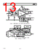
14 / 22 page  AMP01 –14– REV. D If heavy output currents are expected and the load is situated some distance from the amplifier, voltage drops due to track or wire resistance will cause errors. Voltage drops are particularly troublesome when driving 50 Ω loads. Under these conditions, the sense and reference terminals can be used to “remote sense” the load as shown in Figure 33. This method of connection puts the I ×R drops inside the feedback loop and virtually eliminates the error. An unbalance in the lead resistances from the sense and reference pins does not degrade CMR, but will change the output offset voltage. For example, a large unbalance of 3 Ω will change the output offset by only 1 mV. DRIVING 50 LOADS Output currents of 50 mA are guaranteed into loads of up to 50 Ω and 26 mA into 500 Ω. In addition, the output is stable and free from oscillation even with a high load capacitance. The combination of these unique features in an instrumentation amplifier allows low-level transducer signals to be conditioned and directly transmitted through long cables in voltage or cur- rent form. Increased output current brings increased internal dissipation, especially with 50 Ω loads. For this reason, the power-supply connections are split into two pairs; pins 10 and 13 connect to the output stage only and pins 11 and 12 provide power to the input and following stages. Dual supply pins allow dropper resistors to be connected in series with the output stage so excess power is dissipated outside the package. Additional decoupling is necessary between pins 10 and 13 to ground to maintain stability when dropper resistors are used. Figure 34 shows a complete circuit for driving 50 Ω loads. AMP01 +IN –IN RG 18 1 2 3 14 15 12 13 7 9 8 10 11 V– V+ SENSE REFERENCE * * OUTPUT GROUND TWISTED PAIRS REMOTE LOAD IN4148 DIODES ARE OPTIONAL. DIODES LIMIT THE OUTPUT VOLTAGE EXCURSION IF SENSE AND/OR REFERENCE LINES BECOME DISCONNECTED FROM THE LOAD. * RS Figure 33. Remote Load Sensing +IN –IN RG AMP01 14 15 12 13 7 9 8 10 11 18 1 2 3 RS 5k R1 130 1W C1 0.047 F 0.047 F +15V SENSE REFERENCE VOUT 3V MAX 50 LOAD C2 0.047 F R2 130 1W 0.047 F –15V POWER BANDWIDTH, G = 100, 130kHz POWER BANDWIDTH, G = 10, 200kHz T.H.D.~0.04% @ 1kHz, 2Vrms VOLTAGE GAIN, G = ( ) 20 RS RG RESISTERS R1 AND R2 REDUCE IC DISSIPATION Figure 34. Driving 50 Ω Loads |
|
|
Enlace URL |
| ¿ALLDATASHEET es útil para Ud.? [ DONATE ] |
Todo acerca de Alldatasheet | Publicidad | Contáctenos | Política de Privacidad | Enlace a la hoja de datos | Intercambio de Enlaces | Lista de Fabricantes All Rights Reserved©Alldatasheet.com |
| Russian : Alldatasheetru.com | Korean : Alldatasheet.co.kr | Spanish : Alldatasheet.es | French : Alldatasheet.fr | Italian : Alldatasheetit.com Portuguese : Alldatasheetpt.com | Polish : Alldatasheet.pl | Vietnamese : Alldatasheet.vn Indian : Alldatasheet.in | Mexican : Alldatasheet.com.mx | British : Alldatasheet.co.uk | New Zealand : Alldatasheet.co.nz |
|
Family Site : ic2ic.com |
icmetro.com |
 Mexican ▼
 English
 Chinese
 German
 Japanese
 Russian
 Korean
 Spanish
 French
 Italian
 Portuguese
 Polish
 Vietnamese
 Indian
 Mexican
 British
 New Zealand