|
Motor de Búsqueda de Datasheet de Componentes Electrónicos |
|
|
Motor de Búsqueda de Datasheet de Componentes Electrónicos |
|
ICS9248-114 Datasheet(PDF) 13 Page - Renesas Technology Corp |
|
|
|||||||||||||||||||||||||||||
ICS9248-114 Datasheet(HTML) 13 Page - Renesas Technology Corp |
|
|
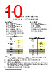
13 / 15 page  ICS9248-114 PD# Timing Diagram The power down selection is used to put the part into a very low power state without turning off the power to the part. PD# is an asynchronous active low input. This signal needs to be synchronized internal to the device prior to powering down the clock synthesizer. Internal clocks are not running after the device is put in power down. When PD# is active low all clocks need to be driven to a low value and held prior to turning off the VCOs and crystal. The power up latency needs to be less than 3 mS. The power down latency should be as short as possible but conforming to the sequence requirements shown below. PCI_STOP# and CPU_STOP# are considered to be don't cares during the power down operations. The REF and 48MHz clocks are expected to be stopped in the LOW state as soon as possible. Due to the state of the internal logic, stopping and holding the REF clock outputs in the LOW state may require more than one clock cycle to complete. PD# \\\\\ rmr-� 2 �� CPUCLKT � 2� 2 CPUCLKC s ss s PCICLK _J 2� 2� 2 vco � 2� -� Crystal � 2�i Notes: 1. All timing is referenced to the Internal CPUCLK (defined as inside the ICS9248-114 device). 2. As shown, the outputs Stop Low on the next falling edge after PD# goes low. 3. PD# is an asynchronous input and metastable conditions may exist. This signal is synchronized inside this part. 4. The shaded sections on the VCO and the Crystal signals indicate an active clock. 5. Diagrams shown with respect to 133MHz. Similar operation when CPU is 100MHz. Third party brands and names are the property of their respective owners. 13 |
|
|
Enlace URL |
| ¿ALLDATASHEET es útil para Ud.? [ DONATE ] |
Todo acerca de Alldatasheet | Publicidad | Contáctenos | Política de Privacidad | Enlace a la hoja de datos | Intercambio de Enlaces | Lista de Fabricantes All Rights Reserved©Alldatasheet.com |
| Russian : Alldatasheetru.com | Korean : Alldatasheet.co.kr | Spanish : Alldatasheet.es | French : Alldatasheet.fr | Italian : Alldatasheetit.com Portuguese : Alldatasheetpt.com | Polish : Alldatasheet.pl | Vietnamese : Alldatasheet.vn Indian : Alldatasheet.in | Mexican : Alldatasheet.com.mx | British : Alldatasheet.co.uk | New Zealand : Alldatasheet.co.nz |
|
Family Site : ic2ic.com |
icmetro.com |
 Mexican ▼
 English
 Chinese
 German
 Japanese
 Russian
 Korean
 Spanish
 French
 Italian
 Portuguese
 Polish
 Vietnamese
 Indian
 Mexican
 British
 New Zealand