 |
Motor de Búsqueda de Datasheet de Componentes Electrónicos |
|
|
Motor de Búsqueda de Datasheet de Componentes Electrónicos |
|
The question interval is too short.
Please try again in a few seconds.

Hello, Please ask a question about BLF177 Datasheet
# Example questions:
➢ In the class-b test circuit, what is the value of resistor r6?
➢ What is the typical power gain (gp) in db for the class-b operation at a frequency of 108 mhz?
➢ What material is the dielectric of the printed circuit board used for the striplines in both the class-b and class-a/b test circuits?
| Part No. | BLF177 |
| Manufacturer | NXP |
| Size | 321 Kbytes |
| Pages | 19 pages |
| Description | HF/VHF power MOS transistor |


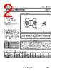
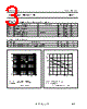
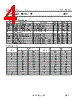

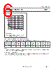




1. General Information & Purpose
️· Device: NXP BLF177 Power MOSFET
️· Application: High-frequency (HF/VHF) amplification, likely for RF applications.
️· Datasheet Section: This appears to be an excerpt from a complete datasheet, covering aspects of performance in both Class-A and Class-B amplifier configurations.
2. Class-A Operation Highlights:
️· Typical Test Setup: Implied a common source configuration (though not explicitly stated in all sections).
️· Performance Metrics:
- *Gain (Gp):* Power gain in dB.
- *Efficiency (ηD):* Drain efficiency (percentage).
- *Input Impedance (Zin):* Series input impedance.
- *Power (PL):* Load power in Watts.
️· Key Parameters (From Tables and Figures):
- VDS: Drain-Source Voltage (typically 50V).
- IDQ: Drain Quiescent Current (0.1A to 1A depending on operating class)
- GS: Gate-Source Resistance (often 6.25 or 15.8 ohms).
- Frequency: 108 MHz is a common test frequency.
- Figures 14-16 demonstrate performance curves for power gain, efficiency, and load power versus frequency and load power.
️· Circuit Components: List of components used in the Class A circuit, with values and part numbers (see 'List of components Class-A test circuit').
3. Class-B Operation Highlights:
️· Test Conditions: Similar to Class-A, common source configuration, but with different bias conditions.
️· Key Differences: Class-B operates with a different quiescent current (IDQ = 100 mA) and often different gate-source resistance (RGS = 15.8 ohms).
️· Performance Metrics: Same metrics as Class-A (Gp, ηD, PL, Zin).
️· Key Parameters (From Tables and Figures):
- VDS: Drain-Source Voltage (typically 50V).
- IDQ: Drain Quiescent Current (100mA).
- GS: Gate-Source Resistance (typically 15.8 ohms).
- Figures 16-18 demonstrate performance curves.
️· Circuit Components: A different list of circuit components is used in the Class B circuit.
4. Specific Data & Key Observations:
️· Input Impedance: Figure 14 shows input impedance varies with frequency.
️· Efficiency: Efficiency is heavily dependent on the load power (PL).
️· Load Power vs. Input Power: Figure 18 illustrates how load power increases with input power in Class-B.
️· Circuit Design Considerations: The lists of components for both Class-A and Class-B configurations are critical for replicating the test setups.
5. Component Lists:
️· Detailed lists of resistors, capacitors, inductors, and potentiometers used in the Class-A and Class-B test circuits are provided. These lists include values, dimensions, and catalogue numbers.
️· The use of American Technical Ceramics (ATC) capacitors (Type 100B) is noted, implying a requirement for high-quality capacitance.
️· The use of Rogers 5880 PCB material is also indicated.
IMPORTANT NOTES AND LIMITATIONS OF THIS SUMMARY:
️· Partial Datasheet: This is *not* the complete datasheet. Important sections like absolute maximum ratings, pinout descriptions, thermal characteristics, and detailed electrical characteristics are missing. You MUST consult the full datasheet for safe and reliable operation.
️· Test Conditions: The data presented is for specific test conditions. Performance in your actual application may vary significantly.
️· Simulation and Verification: The provided data is a starting point. You're strongly advised to simulate your circuit and verify the MOSFET's performance before committing to a final design.
️· Component Tolerances: The provided values are nominal. Component tolerances will affect performance.
️· Thermal Management: MOSFETs generate heat. Adequate heat sinking is essential for reliable operation, especially at higher power levels. This aspect isn't covered in this excerpt.
️· Layout Sensitivity: High-frequency circuits are often sensitive to PCB layout. Careful attention to layout techniques is crucial.
️· Bias Circuit: Proper biasing is critical for achieving the desired operating class and performance.
1. General Information & Purpose
️· Device: NXP BLF177 Power MOSFET
️· Application: High-frequency (HF/VHF) amplification, likely for RF applications.
️· Datasheet Section: This appears to be an excerpt from a complete datasheet, covering aspects of performance in both Class-A and Class-B amplifier configurations.
2. Class-A Operation Highlights:
️· Typical Test Setup: Implied a common source configuration (though not explicitly stated in all sections).
️· Performance Metrics:
- *Gain (Gp):* Power gain in dB.
- *Efficiency (ηD):* Drain efficiency (percentage).
- *Input Impedance (Zin):* Series input impedance.
- *Power (PL):* Load power in Watts.
️· Key Parameters (From Tables and Figures):
- VDS: Drain-Source Voltage (typically 50V).
- IDQ: Drain Quiescent Current (0.1A to 1A depending on operating class)
- GS: Gate-Source Resistance (often 6.25 or 15.8 ohms).
- Frequency: 108 MHz is a common test frequency.
- Figures 14-16 demonstrate performance curves for power gain, efficiency, and load power versus frequency and load power.
️· Circuit Components: List of components used in the Class A circuit, with values and part numbers (see 'List of components Class-A test circuit').
3. Class-B Operation Highlights:
️· Test Conditions: Similar to Class-A, common source configuration, but with different bias conditions.
️· Key Differences: Class-B operates with a different quiescent current (IDQ = 100 mA) and often different gate-source resistance (RGS = 15.8 ohms).
️· Performance Metrics: Same metrics as Class-A (Gp, ηD, PL, Zin).
️· Key Parameters (From Tables and Figures):
- VDS: Drain-Source Voltage (typically 50V).
- IDQ: Drain Quiescent Current (100mA).
- GS: Gate-Source Resistance (typically 15.8 ohms).
- Figures 16-18 demonstrate performance curves.
️· Circuit Components: A different list of circuit components is used in the Class B circuit.
4. Specific Data & Key Observations:
️· Input Impedance: Figure 14 shows input impedance varies with frequency.
️· Efficiency: Efficiency is heavily dependent on the load power (PL).
️· Load Power vs. Input Power: Figure 18 illustrates how load power increases with input power in Class-B.
️· Circuit Design Considerations: The lists of components for both Class-A and Class-B configurations are critical for replicating the test setups.
5. Component Lists:
️· Detailed lists of resistors, capacitors, inductors, and potentiometers used in the Class-A and Class-B test circuits are provided. These lists include values, dimensions, and catalogue numbers.
️· The use of American Technical Ceramics (ATC) capacitors (Type 100B) is noted, implying a requirement for high-quality capacitance.
️· The use of Rogers 5880 PCB material is also indicated.
IMPORTANT NOTES AND LIMITATIONS OF THIS SUMMARY:
️· Partial Datasheet: This is *not* the complete datasheet. Important sections like absolute maximum ratings, pinout descriptions, thermal characteristics, and detailed electrical characteristics are missing. You MUST consult the full datasheet for safe and reliable operation.
️· Test Conditions: The data presented is for specific test conditions. Performance in your actual application may vary significantly.
️· Simulation and Verification: The provided data is a starting point. You're strongly advised to simulate your circuit and verify the MOSFET's performance before committing to a final design.
️· Component Tolerances: The provided values are nominal. Component tolerances will affect performance.
️· Thermal Management: MOSFETs generate heat. Adequate heat sinking is essential for reliable operation, especially at higher power levels. This aspect isn't covered in this excerpt.
️· Layout Sensitivity: High-frequency circuits are often sensitive to PCB layout. Careful attention to layout techniques is crucial.
️· Bias Circuit: Proper biasing is critical for achieving the desired operating class and performance.
| Part No. | BLF177 |
| Manufacturer | NXP |
| Size | 321 Kbytes |
| Pages | 19 pages |
| Description | HF/VHF power MOS transistor |
| ¿ALLDATASHEET es útil para Ud.? [ DONATE ] |
Todo acerca de Alldatasheet | Publicidad | Contáctenos | Política de Privacidad | Enlace a la hoja de datos | Intercambio de Enlaces | Lista de Fabricantes All Rights Reserved©Alldatasheet.com |
| Russian : Alldatasheetru.com | Korean : Alldatasheet.co.kr | Spanish : Alldatasheet.es | French : Alldatasheet.fr | Italian : Alldatasheetit.com Portuguese : Alldatasheetpt.com | Polish : Alldatasheet.pl | Vietnamese : Alldatasheet.vn Indian : Alldatasheet.in | Mexican : Alldatasheet.com.mx | British : Alldatasheet.co.uk | New Zealand : Alldatasheet.co.nz |
|
Family Site : ic2ic.com |
icmetro.com |
 Mexican ▼
  English
 Chinese
 German
 Japanese
 Russian
 Korean
 Spanish
 French
 Italian
 Portuguese
 Polish
 Vietnamese
 Indian
 British
 New Zealand