|
Motor de Búsqueda de Datasheet de Componentes Electrónicos |
|
|
Motor de Búsqueda de Datasheet de Componentes Electrónicos |
|
7708 Datasheet(PDF) 10 Page - Power Integrations, Inc. |
|
|
|||||||||||||||||||||||||||||
7708 Datasheet(HTML) 10 Page - Power Integrations, Inc. |
|
|
10 / 42 page 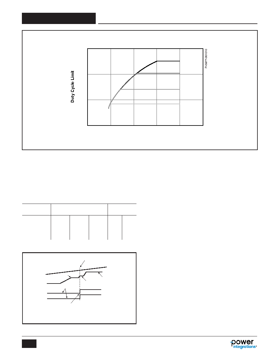 Rev. B 04/15 10 TFS7701-7708 www.power.com A resistor R FB is connected from the BYPASS pin to the FEEDBACK pin. This resistor feeds current into the FEEDBACK pin (pin voltage is clamped to approximately 1 V during this detection period). The current into the FEEDBACK pin is determined by the value of the resistor, and thus the input current (and indirectly the resistor value), select an internal current limit according to the following table. Main Line Undervoltage Detection (UV) The LINE-SENSE pin resistor is connected to V IN and generates a current signal proportional to V IN. The LINE-SENSE pin voltage is held by the device at 1.2 V. The LINE-SENSE pin current signal is used to trigger under/overvoltage thresholds for both the standby and main converters. Assuming a LINE-SENSE pin resistor of 4 M W, the standby will begin operating when the LINE-SENSE pin current exceeds the (I L(SB-UVON)) threshold, nominally approximately 100 V. However the main is still held in the off-state, until the LINE-SENSE pin current exceeds the (I L(MA-UVON)) threshold, nominally 336 V for 4 MW. There is hysteresis for both main and standby undervoltage-off thresholds, to allow sufficient margin to avoid accidental triggering, and to provide sufficient margin to meet hold-up time requirements. Bear in mind that the main converter may start to loose regulation before it finally shuts down. This is because the dynamic duty cycle limit may clamp the duty cycle below that required for regulation at lower input voltages. Once the input voltage falls below the 215 V (I L(MA_UVOFF)) threshold, the main will shutdown but standby will continue to operate. The standby will turn off when the input voltage drops below approximately 40 V (I L(SB-UVON)). Figure 9. Current Limit Selection. Table 3. FEEDBACK Pin Main Current Limit Selection. I FB (Threshold) I LIMIT (Main) R FB(SELECT) (1%) 0.0 - 5.1 mA L1 70% mA Open k W 5.1 - 11.9 mA L2 90% mA 511.0 k W 11.9 - 23.8 mA L3 100% mA 232.0 k W UV(ON)STANDBY, I(L) = 25 µA 4.7 V 1 V 5.7 V I(L) V(BP) V(FB) V(EN) T SELECT - current limit selection occurs here during device start-up and before power supply switching 2.7 V 2.7 V 6.0 V after standby acheives regulation PI-6973-022513 Figure 8. Duty Cycle Limit vs. Ratio of R Pin Current Over L Pin Current. 0.5 1.0 1.5 2.0 3.0 2.5 IR/IL 0.7 0.6 0.5 0.4 IL = 60 µA IL = 90 µA IL = 100 µA IL = 115 µA |
|
Enlace URL |
| ¿ALLDATASHEET es útil para Ud.? [ DONATE ] |
Todo acerca de Alldatasheet | Publicidad | Contáctenos | Política de Privacidad | Enlace a la hoja de datos | Intercambio de Enlaces | Lista de Fabricantes All Rights Reserved©Alldatasheet.com |
| Russian : Alldatasheetru.com | Korean : Alldatasheet.co.kr | Spanish : Alldatasheet.es | French : Alldatasheet.fr | Italian : Alldatasheetit.com Portuguese : Alldatasheetpt.com | Polish : Alldatasheet.pl | Vietnamese : Alldatasheet.vn Indian : Alldatasheet.in | Mexican : Alldatasheet.com.mx | British : Alldatasheet.co.uk | New Zealand : Alldatasheet.co.nz |
|
Family Site : ic2ic.com |
icmetro.com |
 Mexican ▼
 English
 Chinese
 German
 Japanese
 Russian
 Korean
 Spanish
 French
 Italian
 Portuguese
 Polish
 Vietnamese
 Indian
 Mexican
 British
 New Zealand