|
Motor de Búsqueda de Datasheet de Componentes Electrónicos |
|
|
Motor de Búsqueda de Datasheet de Componentes Electrónicos |
|
7708 Datasheet(PDF) 16 Page - Power Integrations, Inc. |
|
|
|||||||||||||||||||||||||||||
7708 Datasheet(HTML) 16 Page - Power Integrations, Inc. |
|
|
16 / 42 page 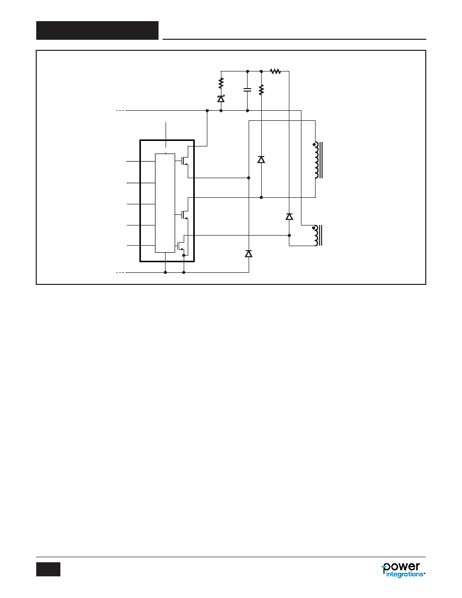 Rev. B 04/15 16 TFS7701-7708 www.power.com Figure 15. Standard Values for Clamp-to-Rail Scheme. These Work Well for all Power Ranges and both 66 and 132 kHz. Using Standard Recovery Diodes for CR2 and CR3 Allow for Partial Recycling of Leakage Inductance Energy and Improve Efficiency. R1 and R2 Limit Peak Reverse Current and Provide Some High Frequency Damping, and R3 Allows VZ1 to Work as a “Bleed” Instead of a Hard Clamp, to Improve Efficiency. HD HS D G S HiperTFS-2 VDDH R L FB EN BP DSB CONTROL PI-7019-102513 R1 4.7 Ω B+ R2 2.2 Ω C1 2.2 nF D2 1N4007G D3 1N4007G D1 UF4007 R3 100 Ω VZ1 150 V Standby Primary Main Primary B- Output Choke The use of iron powder (lower cost) or Sendust (“Kool-Mu”, higher efficiency) core material is recommended. The inductance of a powdered iron or Sendust core varies significantly with load. At light load the inductance is much higher than at full load, which allows a forward converter to remain in continuous conduction mode (CCM), down to very light load. For multiple outputs the inductor turns ratio should be the same as the main transformer secondary. Spreading the windings equally throughout the toroid improves coupling and cross- regulation. Output Capacitors The output capacitors in a forward converter do not see high AC ripple currents. Very-low ESR capacitors are not necessary. However the ESR of the capacitors have a direct effect on output ripple voltage (if no post-filter is used) and on fast load- transient response. The capacitance has an effect on medium- speed load-transient response. Polymer (solid electrolyte) capacitors are not necessary but can be used for output capacitors if very small size is required. However, their small capacitance may require an additional, low-cost (moderate ESR) electrolytic capacitor in parallel, to maintain sufficient capacitance for loop stabilization and transient response. Standby Mode Consumption To improve the standby converter’s light load efficiency, a 7.5 k W bias resistor should be connected from V AUX to the BYPASS pin. This will turn off the internal high-voltage current source that otherwise powers the BYPASS pin. Heat Sinking The HiperTFS-2 package is eSIP-16F. There is a metal exposed pad that provides a low thermal resistance path to the heat sink for the low-side main MOSFET and standby power MOSFET. There is also an over-molded, electrically isolated section on the back of the package that provides isolation between the heat sink and the internal high-side main MOSFET. The heat sink temperature behind the device should not exceed 95 °C to provide sufficient thermal margin to avoid activating over- temperature shutdown. The device does not require Insulation pad (SIL pad). See Power Integrations’ website “Mounting with Plastic and Metal Clips”. Clip to provide 20N of clamping force (15N min, 50N max). Thermal heat sink compound is required for optimal thermal performance. |
|
Enlace URL |
| ¿ALLDATASHEET es útil para Ud.? [ DONATE ] |
Todo acerca de Alldatasheet | Publicidad | Contáctenos | Política de Privacidad | Enlace a la hoja de datos | Intercambio de Enlaces | Lista de Fabricantes All Rights Reserved©Alldatasheet.com |
| Russian : Alldatasheetru.com | Korean : Alldatasheet.co.kr | Spanish : Alldatasheet.es | French : Alldatasheet.fr | Italian : Alldatasheetit.com Portuguese : Alldatasheetpt.com | Polish : Alldatasheet.pl | Vietnamese : Alldatasheet.vn Indian : Alldatasheet.in | Mexican : Alldatasheet.com.mx | British : Alldatasheet.co.uk | New Zealand : Alldatasheet.co.nz |
|
Family Site : ic2ic.com |
icmetro.com |
 Mexican ▼
 English
 Chinese
 German
 Japanese
 Russian
 Korean
 Spanish
 French
 Italian
 Portuguese
 Polish
 Vietnamese
 Indian
 Mexican
 British
 New Zealand