|
Motor de Búsqueda de Datasheet de Componentes Electrónicos |
|
|
Motor de Búsqueda de Datasheet de Componentes Electrónicos |
|
7708 Datasheet(PDF) 22 Page - Power Integrations, Inc. |
|
|
|||||||||||||||||||||||||||||
7708 Datasheet(HTML) 22 Page - Power Integrations, Inc. |
|
|
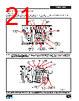
22 / 42 page  Rev. B 04/15 22 TFS7701-7708 www.power.com PI-7016-052913 Transformer Secondary Pins High-Current Loop Area Output Diodes Figure 26. Layout of Forward Transformer Secondary and Output Diodes. The Diodes and Secondary Pins Should be Mounted Close Together, to Minimize the Loop Area They Form. 400 200 0 2.8 µs Figure 27. Drain Voltage at Zero Load, to Measure Magnetizing Resonant Frequency. In the Above Example, the Cursors Were Set to Measure a Half-Cycle. The Resonant Frequency calculates as f O = 1/(2.8 ms × 2) = 177 kHz. Figure 29. Low-Line Operation (Just Above Main UV-OFF Threshold), with Load in Borderline Continuous Mode. The Output will be out of Regulation. This is the Condition to test for Complete Core Reset. The Soft Corner in the (HS) Voltage at Turn-On Signifies Reversal of Magnetizing Current and thus Complete Core Reset. The Sharp Corner in the Drain (D) Waveform Signifies Hard-Reverse Recovery in the Drain (Standard-Recovery) Clamp Rectifier. This is Acceptable for Transient Conditions (e.g., Hold-Up Time) 200 0 400 600 1.5 1 0 0.5 Drain Current Snubber Clamp Voltage Turn-Off Edge Turn-On Edge High-Side Main Drain High-Side VCOSS VBULK Shelf Figure 28. Typical Full Load Waveforms of the Main Drian. High-Side MOSFET Source, and Drain Current. Main Converter Typical Waveforms Main Transformer Primary Inductance and Resonant Frequency At zero load, check the resonant frequency visible in the Drain voltage. This is the resonant frequency between the primary inductance and the total capacitance reflected to the primary (MOSFETs, transformer self-capacitance, output diode capacitances). See Figure 27. A low resonant frequency can prevent proper core reset at low-line and continuous-mode light load, and can lead to core staircase saturation. See Figure 29. Too much primary inductance causes the Drain rise time to be very slow, eroding core reset volt-seconds. If the measured resonant frequency is below 120 kHz (for 132 kHz operation), or below 60 kHz (for 66 kHz operation), reduce transformer primary inductance by increasing core gap. This initial test is a rule of thumb. The final test is to check for complete core reset at very low input voltage (just above the main UVLO threshold), at a light load that is just above borderline continuous operation. Reducing primary inductance below the value necessary for complete core reset, will reduce efficiency. Full Load Figure 16 shows the typical full-load waveform. Check high- side V COSS at turn-on. It is typically below 40% of the input voltage. If it is greater, ensure that the low-side MOSFET clamp diode is a standard-recovery (slow) rectifier (1N4007) and the high-side MOSFET clamp diode (to ground) is an ultrafast type (e.g., UF4005). Reducing the primary inductance by 20-30% will also decrease this voltage, and in some cases may improve full load efficiency. Flyback Standby Converter The data sheet standby max power rating represents the minimum practical continuous output power level that can be obtained under the following assumed conditions: 1. The minimum DC input voltage is 115 V. 200 2 µs/div 0 400 600 0.4 0 0.2 Soft Corner in (HS) Voltage, Flux goes Negative, no Risk of Saturation Drain (D) Clamp Diode Large Reverse Recovery Current Sharp Corner (D) Voltage at Turn-On |
|
Enlace URL |
| ¿ALLDATASHEET es útil para Ud.? [ DONATE ] |
Todo acerca de Alldatasheet | Publicidad | Contáctenos | Política de Privacidad | Enlace a la hoja de datos | Intercambio de Enlaces | Lista de Fabricantes All Rights Reserved©Alldatasheet.com |
| Russian : Alldatasheetru.com | Korean : Alldatasheet.co.kr | Spanish : Alldatasheet.es | French : Alldatasheet.fr | Italian : Alldatasheetit.com Portuguese : Alldatasheetpt.com | Polish : Alldatasheet.pl | Vietnamese : Alldatasheet.vn Indian : Alldatasheet.in | Mexican : Alldatasheet.com.mx | British : Alldatasheet.co.uk | New Zealand : Alldatasheet.co.nz |
|
Family Site : ic2ic.com |
icmetro.com |
 Mexican ▼
 English
 Chinese
 German
 Japanese
 Russian
 Korean
 Spanish
 French
 Italian
 Portuguese
 Polish
 Vietnamese
 Indian
 Mexican
 British
 New Zealand