|
Motor de Búsqueda de Datasheet de Componentes Electrónicos |
|
|
Motor de Búsqueda de Datasheet de Componentes Electrónicos |
|
ADRF6655ACPZ-R7 Datasheet(PDF) 17 Page - Analog Devices |
|
|
|||||||||||||||||||||||||||||
ADRF6655ACPZ-R7 Datasheet(HTML) 17 Page - Analog Devices |
|
|
17 / 44 page 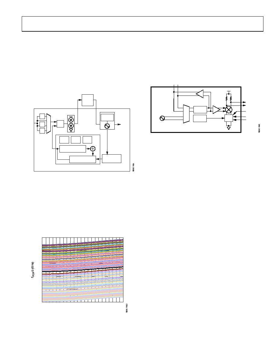 ADRF6655 Rev. 0 | Page 17 of 44 CIRCUIT DESCRIPTION The ADRF6655 can be subdivided into a PLL and VCO block and a mixer block. A detailed circuit description for each block follows. PLL AND VCO BLOCK The PLL and VCO block, shown in Figure 49, is made up of a reference input block, a phase and frequency detector (PFD), a charge pump, a VCO, and a divide-by-N modulus block. An off-chip loop filter completes the loop. LOOP FILTER PRESCALER ADRF6655 PLL BLOCK DIAGRAM BAND SELECT TO MIXER BLOCk CP CP VTUNE PFD REFIN FRAC MOD INT PROGRAMMABLE DIVIDER THIRD-ORDER INTERPOLATOR ×2 ÷2 ÷4 Figure 49. PLL and VCO Block The VCO is implemented with a single core that consists of 64 overlapping bands, as shown in Figure 50. The correct band is selected automatically by the VCO band calibration circuit when Register R0, Register R1, or Register R2 is programmed. The VCO band selection takes roughly 4000 PFD cycles. During calibration, an internal mux is used to disconnect the VCO input voltage from the VTUNE pin and apply an internal reference voltage for calibration. When calibration is complete, the VCO input voltage is reconnected to the VTUNE pin and normal PLL operation resumes. 1.4 1.6 1.8 2.0 2.2 2.4 0.51.01.52.0 2.5 VTUNE (V) Figure 50. fVCO/2 vs. Tuning Voltage for All 64 Bands The VCO operates at twice the LO frequency for improved isolation. The nominal value of Kv is 75 MHz/V at the VCO output. As the VCO band is changed from 0 to 63, the size of the varactor is also changed, thus maintaining a roughly constant Kv across the entire operating range. RF MIXER BLOCK VCC LO 133 Ω 133 Ω VCO ADRF6655 MIXER BLOCK ÷2 OR ÷3 SIF CDAC V2I OUTN OUTP RFIN IP3SET Figure 51. Mixer Block The mixer portion of the ADRF6655, shown in Figure 51, consists of an LO signal chain, an RF voltage-to-current (V-to-I) converter, and a mixer core. The LO chain receives a signal from either the internal VCO or an external LO source. This LO signal then passes through a frequency divider, which can be set to divide-by-2 or divide-by-3, depending on the desired LO frequency. The differential RF inputs are converted into currents by the V-to-I converter and fed into the mixer core. A pair of 133 Ω pull-up resistors are used to present a ~250 Ω source impedance at the IF output. LO Signal Chain The LO chain consists of a mux that selects between the internal VCO and an external LO source. The LO signal can then be divided by 2 or divided by 3, providing a wide range of LO frequencies from 1050 MHz to 2300 MHz. A buffer then drives this divided down signal to the mixer core. The LO signal can also be observed via the LO I/O port when the internal VCO is selected. When the external LO buffer is enabled, the supply current and die temperature increase, resulting in a slight degradation of RF performance. In normal operation mode, the external LO buffer should be disabled to help minimize power consumption and provide optimal RF performance. |
|
Enlace URL |
| ¿ALLDATASHEET es útil para Ud.? [ DONATE ] |
Todo acerca de Alldatasheet | Publicidad | Contáctenos | Política de Privacidad | Enlace a la hoja de datos | Intercambio de Enlaces | Lista de Fabricantes All Rights Reserved©Alldatasheet.com |
| Russian : Alldatasheetru.com | Korean : Alldatasheet.co.kr | Spanish : Alldatasheet.es | French : Alldatasheet.fr | Italian : Alldatasheetit.com Portuguese : Alldatasheetpt.com | Polish : Alldatasheet.pl | Vietnamese : Alldatasheet.vn Indian : Alldatasheet.in | Mexican : Alldatasheet.com.mx | British : Alldatasheet.co.uk | New Zealand : Alldatasheet.co.nz |
|
Family Site : ic2ic.com |
icmetro.com |
 Mexican ▼
 English
 Chinese
 German
 Japanese
 Russian
 Korean
 Spanish
 French
 Italian
 Portuguese
 Polish
 Vietnamese
 Indian
 Mexican
 British
 New Zealand