|
Motor de Búsqueda de Datasheet de Componentes Electrónicos |
|
|
Motor de Búsqueda de Datasheet de Componentes Electrónicos |
|
AD7011 Datasheet(PDF) 8 Page - Analog Devices |
|
|
|||||||||||||||||||||||||||||
AD7011 Datasheet(HTML) 8 Page - Analog Devices |
|
|
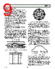
8 / 12 page  AD7011 REV. B –8– TERMINOLOGY Error Vector Magnitude This is a measure of the rms error vector introduced by the AD7011 where signal error vector is defined as the rms devia- tion of a transmitted symbol from its ideal position when filtered by an Ideal RRC Receive filter, as illustrated in Figure 8. Gain Matching Between Channels The is the gain matching between the I and Q outputs, measured when transmitting all zeros. Offset Vector Magnitude This is a measure of the offset vector introduced by the AD7011 as illustrated in Figure 8. The offset vector is calculated so as to minimize the rms error vector for each of the constellation points. Output Signal Range and Different Output Range The output signal range is the output voltage swing and dc bias level for each of the analog outputs. The different output range is the difference between ITx and ITx for the I channel and the difference between QTx and QTx for the Q Channel. IS-54 Spurious Power This is the rms sum of the spurious power measured at multiples of 30 kHz, in a root raised cosine window of ±16.4 kHz, relative to twice the rms power in a RRC window in the 0 to 16.4 kHz band. Signal Vector Magnitude This is the radius of the IQ constellation diagram as illustrated in Figure 8. Signal to (Noise + Distortion) Ratio This is the measured ratio of signal to (noise + distortion) at the output of the transmit I and Q DACs. The signal is the rms amplitude of the fundamental. Noise is the rms sum of all non- fundamental signals up to half the sampling frequency (fS/2), excluding dc. The ratio is dependent upon the number of quantization levels in the digitization process; the more levels, the smaller the quantization noise. The theoretical signal to (noise distortion) ratio for a sine wave is given by: SNR = (6.02N + 1.76) dB where N is the number of bits. Thus for an ideal 10-bit con- verter, SNR = 61.96 dB. I Q ERROR VECTOR OFFSET VECTOR 0,0 SIGNAL VECTOR Figure 8. |
|
|
Enlace URL |
| ¿ALLDATASHEET es útil para Ud.? [ DONATE ] |
Todo acerca de Alldatasheet | Publicidad | Contáctenos | Política de Privacidad | Enlace a la hoja de datos | Intercambio de Enlaces | Lista de Fabricantes All Rights Reserved©Alldatasheet.com |
| Russian : Alldatasheetru.com | Korean : Alldatasheet.co.kr | Spanish : Alldatasheet.es | French : Alldatasheet.fr | Italian : Alldatasheetit.com Portuguese : Alldatasheetpt.com | Polish : Alldatasheet.pl | Vietnamese : Alldatasheet.vn Indian : Alldatasheet.in | Mexican : Alldatasheet.com.mx | British : Alldatasheet.co.uk | New Zealand : Alldatasheet.co.nz |
|
Family Site : ic2ic.com |
icmetro.com |
 Mexican ▼
 English
 Chinese
 German
 Japanese
 Russian
 Korean
 Spanish
 French
 Italian
 Portuguese
 Polish
 Vietnamese
 Indian
 Mexican
 British
 New Zealand