|
Motor de Búsqueda de Datasheet de Componentes Electrónicos |
|
|
Motor de Búsqueda de Datasheet de Componentes Electrónicos |
|
LTC1735CF Datasheet(PDF) 12 Page - Linear Technology |
|
|
|||||||||||||||||||||||||||||
LTC1735CF Datasheet(HTML) 12 Page - Linear Technology |
|
|
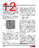
12 / 32 page  12 LTC1735 1735fc The internal oscillator runs at its nominal frequency (fO) when the FCB pin is pulled high to INTVCC or connected to ground. Clocking the FCB pin above and below 0.8V will cause the internal oscillator to injection lock to an external clock signal applied to the FCB pin with a frequency between 0.9fO and 1.3fO. The clock high level must exceed 1.3V for at least 0.3 µs and the clock low level must be less than 0.3V for at least 0.3 µs. The top MOSFET turn-on will synchronize with the rising edge of the clock. Attempting to synchronize to too high an external fre- quency (above 1.3fO) can result in inadequate slope com- pensation and possible loop instability. If this condition exists simply lower the value of COSC so fEXT = fO according to Figure 2. APPLICATIO S I FOR ATIO of smaller inductor and capacitor values. So why would anyone ever choose to operate at lower frequencies with larger components? The answer is efficiency. A higher frequency generally results in lower efficiency because of MOSFET gate charge losses. In addition to this basic trade off, the effect of inductor value on ripple current and low current operation must also be considered. The inductor value has a direct effect on ripple current. The inductor ripple current ∆IL decreases with higher induc- tance or frequency and increases with higher VIN or VOUT: ∆I fL V V V L OUT OUT IN = 1 1 ()( ) – Accepting larger values of ∆IL allows the use of low inductances, but results in higher output voltage ripple and greater core losses. A reasonable starting point for setting ripple current is ∆IL= 0.3 to 0.4(IMAX). Remember, the maximum ∆IL occurs at the maximum input voltage. The inductor value also has an effect on low current operation. The transition to low current operation begins when the inductor current reaches zero while the bottom MOSFET is on. Burst Mode operation begins when the average inductor current required results in a peak current below 25% of the current limit determined by RSENSE. Lower inductor values (higher ∆IL) will cause this to occur at higher load currents, which can cause a dip in efficiency in the upper range of low current operation. In Burst Mode operation, lower inductance values will cause the burst frequency to decrease. Inductor Core Selection Once the value for L is known, the type of inductor must be selected. High efficiency converters generally cannot af- ford the core loss found in low cost powdered iron cores, forcing the use of more expensive ferrite, molypermalloy or Kool M µ® cores. Actual core loss is independent of core size for a fixed inductor value, but it is very dependent on inductance selected. As inductance increases, core losses decrease. Unfortunately, increased inductance re- quires more turns of wire and therefore copper losses will increase. Figure 2. Timing Capacitor Value OPERATING FREQUENCY (kHZ) 0 100 200 300 400 500 600 1735 F02 100.0 87.5 75.0 62.5 50.0 37.5 25.0 12.5 0 When synchronized to an external clock, Burst Mode operation is disabled but the inductor current is not allowed to reverse. The 25% minimum inductor current clamp present in Burst Mode operation is removed, providing constant frequency discontinuous operation over the widest possible output current range. In this mode the synchronous MOSFET is forced on once every 10 clock cycles to recharge the bootstrap capacitor. This minimizes audible noise while maintaining reasonably high efficiency. Inductor Value Calculation The operating frequency and inductor selection are inter- related in that higher operating frequencies allow the use Kool M µ is a registered trademark of Magnetics, Inc. |
|
Enlace URL |
| ¿ALLDATASHEET es útil para Ud.? [ DONATE ] |
Todo acerca de Alldatasheet | Publicidad | Contáctenos | Política de Privacidad | Enlace a la hoja de datos | Intercambio de Enlaces | Lista de Fabricantes All Rights Reserved©Alldatasheet.com |
| Russian : Alldatasheetru.com | Korean : Alldatasheet.co.kr | Spanish : Alldatasheet.es | French : Alldatasheet.fr | Italian : Alldatasheetit.com Portuguese : Alldatasheetpt.com | Polish : Alldatasheet.pl | Vietnamese : Alldatasheet.vn Indian : Alldatasheet.in | Mexican : Alldatasheet.com.mx | British : Alldatasheet.co.uk | New Zealand : Alldatasheet.co.nz |
|
Family Site : ic2ic.com |
icmetro.com |
 Mexican ▼
 English
 Chinese
 German
 Japanese
 Russian
 Korean
 Spanish
 French
 Italian
 Portuguese
 Polish
 Vietnamese
 Indian
 Mexican
 British
 New Zealand