|
Motor de Búsqueda de Datasheet de Componentes Electrónicos |
|
|
Motor de Búsqueda de Datasheet de Componentes Electrónicos |
|
LTC1735CF Datasheet(PDF) 19 Page - Linear Technology |
|
|
|||||||||||||||||||||||||||||
LTC1735CF Datasheet(HTML) 19 Page - Linear Technology |
|
|
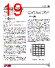
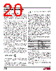
19 / 32 page  19 LTC1735 1735fc tON(MIN) of the LTC1735 (approximately 200ns), the input voltage and inductor value: ∆IL(SC) = tON(MIN)VIN/L The resulting short-circuit current is: I mV R I SC SENSE LSC =+ 30 1 2 ∆ () The current foldback function is always active and is not effected by the current latchoff function. Fault Conditions: Output Overvoltage Protection (Crowbar) The output overvoltage crowbar is designed to blow a system fuse in the input lead when the output of the regulator rises much higher than nominal levels. This condition causes huge currents to flow, much greater than in normal operation. This feature is designed to protect against a shorted top MOSFET; it does not protect against a failure of the controller itself. The comparator (OV in the Functional Diagram) detects overvoltage faults greater than 7.5% above the nominal output voltage. When this condition is sensed the top MOSFET is turned off and the bottom MOSFET is forced on. The bottom MOSFET remains on continuously for as long as the 0V condition persists; if VOUT returns to a safe level, normal operation automatically resumes. Note that dynamically changing the output voltage may cause overvoltage protection to be momentarily activated during programmed output voltage decreases. This will not cause permanent latchoff nor will it disrupt the desired voltage change. With soft-latch overvoltage protection, dynamically changing the output voltage is allowed and the overvoltage protection tracks the newly programmed output voltage, always protecting the load. Minimum On-Time Considerations Minimum on-time tON(MIN) is the smallest amount of time that the LTC1735 is capable of turning the top MOSFET on and off again. It is determined by internal timing delays and the gate charge required to turn on the top MOSFET. Low duty cycle applications may approach this minimum on- time limit and care should be taken to ensure that: t V Vf ON MIN OUT IN () () < If the duty cycle falls below what can be accommodated by the minimum on-time, the LTC1735 will begin to skip cycles. The output voltage will continue to be regulated, but the ripple current and voltage will increase. The minimum on-time for the LTC1735 in a properly configured application is generally less than 200ns. How- ever, as the peak sense voltage decreases, the minimum on-time gradually increases as shown in Figure 7. This is of particular concern in forced continuous applications with low ripple current at light loads. If the duty cycle drops below the minimum on-time limit in this situation, a significant amount of cycle skipping can occur with corre- spondingly larger current and voltage ripple. If an application can operate close to the minimum on- time limit, an inductor must be chosen that is low enough to provide sufficient ripple amplitude to meet the mini- mum on-time requirement. As a general rule, keep the inductor ripple current equal or greater than 30% of IOUT(MAX) at VIN(MAX). APPLICATIO S I FOR ATIO ∆IL/IOUT(MAX) (%) 0 100 150 40 1735 F07 50 0 10 20 30 250 200 Figure 7. Minimum On-Time vs ∆IL |
|
Enlace URL |
| ¿ALLDATASHEET es útil para Ud.? [ DONATE ] |
Todo acerca de Alldatasheet | Publicidad | Contáctenos | Política de Privacidad | Enlace a la hoja de datos | Intercambio de Enlaces | Lista de Fabricantes All Rights Reserved©Alldatasheet.com |
| Russian : Alldatasheetru.com | Korean : Alldatasheet.co.kr | Spanish : Alldatasheet.es | French : Alldatasheet.fr | Italian : Alldatasheetit.com Portuguese : Alldatasheetpt.com | Polish : Alldatasheet.pl | Vietnamese : Alldatasheet.vn Indian : Alldatasheet.in | Mexican : Alldatasheet.com.mx | British : Alldatasheet.co.uk | New Zealand : Alldatasheet.co.nz |
|
Family Site : ic2ic.com |
icmetro.com |
 Mexican ▼
 English
 Chinese
 German
 Japanese
 Russian
 Korean
 Spanish
 French
 Italian
 Portuguese
 Polish
 Vietnamese
 Indian
 Mexican
 British
 New Zealand